17 Aug
2026
Energeks
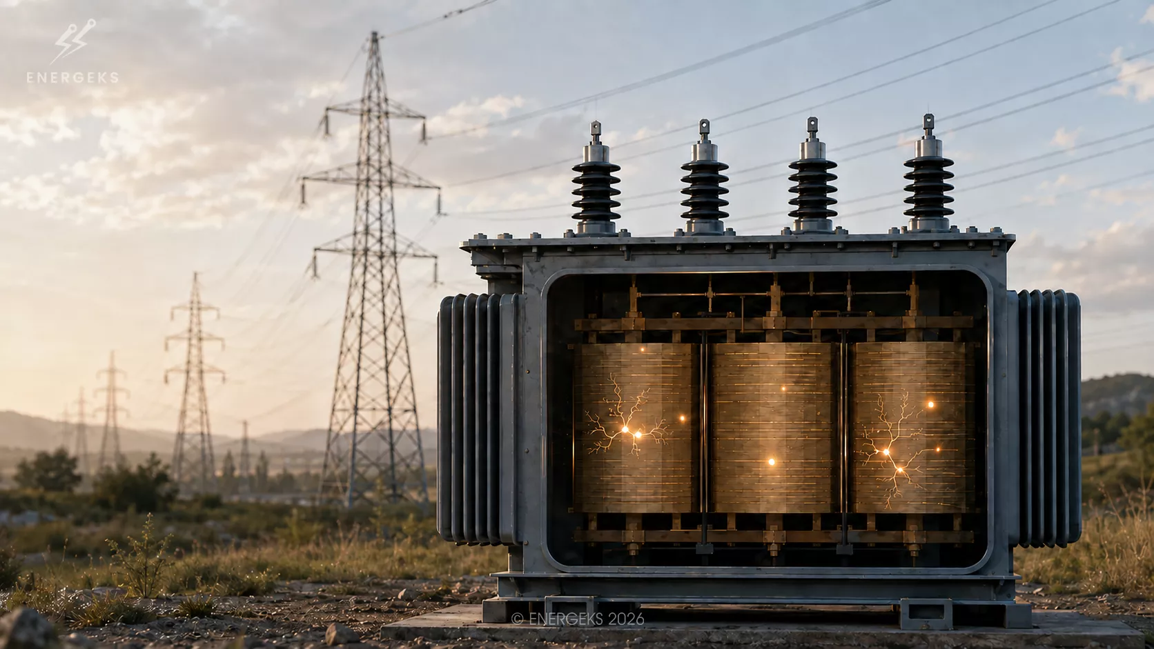
In this article, we explain what partial discharges are, why they occur, what symptoms they can cause, and how they are measured. We will also show why the value in picocoulombs alone is not enough to assess risk.
The light works.
The fridge cools.
The kettle boils water.
Nothing sparks, nothing smokes, no one runs for a fire extinguisher.
You could assume everything is fine.
Now imagine that in one socket, a very small, almost imperceptible sparking appears. Not every time. Sometimes under a higher load.
Sometimes when it is humid in the flat. Sometimes only for a fraction of a second.
Would you still assume there is no problem?
Probably not.
In a transformer, partial discharges—known as PD—can play a similar role. They are small, short-lived and often invisible during a standard inspection.
They do not immediately cause a spectacular breakdown or an instant trip of the device.
Instead, they gradually weaken the insulation.
A bit like a leak in a roof. One drop will not destroy the building. But if it drips every day for many months, the structure starts to soak. Moisture appears, mould, material damage and an increasingly large repair bill.
With partial discharges it is similar. A single pulse does not necessarily mean disaster. Repeated pulses, however, can indicate that a small, invisible degradation mechanism is at work inside the transformer.
And that is precisely why PD is worth detecting while the transformer is still running.
This material is intended for those responsible for maintaining transformers, transformer stations, switchgear and industrial installations. It will also be useful for designers, investors and anyone who wants to better understand what is happening in the insulation of high‑ and medium‑voltage equipment.
After reading, it will be easier to answer the questions:
Is every PD a failure?
Which symptoms should raise concern?
What is the difference between offline measurement and online monitoring?
Why does oil analysis not replace PD measurement?
How to distinguish a real discharge from interference?
What to do when results start to deteriorate?
Reading time: about 9 minutes.
A transformer works thanks to the controlled flow of energy between the windings. The insulation separates elements at different potentials and ensures that current flows where it should.
Under ideal conditions, the electric field is evenly distributed. The insulation retains its properties and the device operates without unwanted phenomena.
Reality is less elegant.
In the insulating material, there may be small gas voids. Delaminations, micro‑cracks, contamination or areas of incorrect geometry can appear. Sometimes the problem arises from ageing, moisture, mechanical stress or unfavourable operating conditions.
At such a point, the electric field strength can become locally too high. A brief discharge then occurs.
It does not cover the entire path between the electrodes. That is why we call it a partial discharge.
It is a bit like a spark jumping in a worn‑out charger. It is not yet a complete short circuit, but the material is already getting a signal that its best years may be slowly passing.
In a transformer, a single discharge lasts very briefly. The problem is the repetition frequency and the location where the phenomenon occurs. If the pulses appear in a critical area of the insulation, they can gradually destroy the material and create paths along which subsequent discharges can spread more easily.
Partial discharges do not need a large hole or visible damage.
Sometimes a microscopic space is enough, where the local electrical conditions differ from those in the rest of the insulation.
One typical location is gas voids in the solid insulation.
Gas has a lower electrical strength than well‑made paper, resin or oil insulation. In a small void, a discharge can therefore occur, even though the entire insulation structure still appears to work correctly.
This can be compared to a pavement.
Most of its surface is stable, but under one fragment a small space has collapsed. A pedestrian may not notice it. A car will also drive over it without a problem. However, every subsequent load will deepen the damage.
The problem can also appear at sharp edges, incorrectly made connections and places where the electric field concentrates more than it should.
In high‑voltage system design, geometry is of great importance.
A sharp conducting element can act like the tip of a pin under pressure. The force is not distributed evenly. It concentrates on a very small surface.
In an electric field, this means a local increase in stress.
Discharges can also be associated with delaminations.
If a gap forms between insulation elements, the way the field is distributed changes. The material no longer works as a uniform barrier.
Over time, a place may develop where PD activity repeats with every voltage cycle.
Moisture also has a lot to say here. Under the influence of moisture, paper insulation loses some of its properties, and ageing processes can accelerate.
In oil‑immersed transformers, moisture moves between the oil and the solid insulation depending on temperature and operating conditions.
That is why a transformer does not always behave the same way under all conditions.
The same system can show different activity at low temperature, different at high load, and different again after a long period of operation in a humid environment.
Partial discharges have one particularly awkward feature: they can develop without spectacular symptoms.
The transformer can still transfer energy correctly.
Voltages can remain within permissible limits. Temperature can look normal. Protection devices do not have to react.
It is a bit like a car that loses air from a tyre very slowly.
For a few days, the driver notices nothing. The car drives. The steering works. The radio plays. Only after some time does information appear that something is wrong.
In the case of a transformer, the first signal may be a change in oil analysis results, an increase in the number of pulses recorded by the monitoring system, or the appearance of an unusual pattern in the phase‑resolved measurement.
Sometimes a characteristic sound, local vibrations or changes in the parameters of auxiliary devices can be observed. These are not, however, symptoms that always occur. The absence of audible noise does not mean the absence of PD.
A human hears part of the frequency spectrum. Measuring equipment can record phenomena lasting nanoseconds. It is a bit like trying to assess the operation of a server by listening to whether the computer makes the right sound. If nothing is heard, it does not yet mean that everything is working perfectly.
Therefore, the most valuable thing is not single observations, but data collected over time.
If the measurement result remains stable, the situation may be less worrying than for a device where activity is gradually increasing. The trend shows the direction. A single number shows only the moment.
In oil‑immersed transformers, an important diagnostic tool is the analysis of gases dissolved in the oil, known as DGA.
During some processes occurring inside the transformer, gases are produced. Their type and proportions can provide information about possible overheating, electric arcs, insulation ageing or discharge activity.
In this case, the oil can be treated as the device's chronicle.
It does not describe every event with minute‑by‑minute accuracy, but it retains traces of processes that took place inside the tank.
DGA is very useful, but it should not be treated as a direct substitute for PD measurement.
Oil analysis can suggest that an electrical phenomenon is occurring in the transformer.
It will not, however, always show its exact location. It will also not tell everything about the pulse frequency, their phase distribution, or whether the source is at the bushing, winding, connection or another part of the insulation.
The best results come from combining data. If DGA indicates electrical activity and PD measurement shows a repetitive pulse pattern, the diagnosis becomes more reliable. If additionally an acoustic or UHF method indicates a specific area, further actions can be planned more precisely.
One test is a clue. Several consistent tests begin to form a story.
The basis of classic measurements is the electrical method described in IEC 60270. The current standard IEC 60270:2025 covers charge‑based measurement of partial discharges at AC voltages up to 500 Hz and at DC voltage. It describes, among other things, measuring quantities, test circuits, calibration and methods of distinguishing discharges from external interference.
One of the most commonly used parameters is the so‑called apparent charge, expressed in picocoulombs, i.e. pC.
Caution is needed here. Apparent charge is not a simple measurement of the energy of the entire process. It is a value determined on the basis of the response of a specific measuring system to a discharge impulse.
It can be compared to measuring noise in a building. A microphone placed against the wall will record a different value than a microphone placed directly at the sound source. If the room acoustics are also changed, the results will also differ.
PD measurement works similarly. The result is influenced by the transformer construction, the distance from the source, the connection method of the apparatus, shielding, system impedance and the level of interference.
The PRPD pattern is also important, i.e. the distribution of pulses relative to the voltage phase. It allows analysis of in which parts of the voltage cycle discharges appear.
Such an image can help recognise the type of phenomenon. Internal, surface, corona discharges and external interference often form different patterns.
The PRPD pattern should not, however, be treated as an automatic device that pronounces a verdict at a single glance. Interpretation requires comparison with other parameters and knowledge of the specific device.
Offline measurement is performed after the transformer is de‑energised. The device is isolated from the grid and the test conditions can be controlled.
This is like a car inspection in a workshop. The mechanic can lift the vehicle, check components from underneath, connect equipment and perform a test under conditions where many variables remain under control.
In the case of offline measurement, the voltage can be gradually increased, the PD inception voltage determined, the intensity of discharges observed and the voltage at which activity ceases checked.
Such a test provides valuable information, especially after transformer production, after repair or before the device is put into service.
It does, however, have a limitation. The transformer is not then operating in its everyday environment. There is no real load, all grid interference can be different, and the temperature and operating conditions differ from those occurring during operation.
Online measurement allows the transformer to be observed during normal operation. Sensors can record high‑frequency pulses, signals in earthing conductors or electromagnetic waves.
This is like observing a car during everyday driving. You can see how it behaves under acceleration, under load, in traffic and on a long journey. The workshop test is important, but daily operation sometimes reveals things that are not visible on the test bench.
Online monitoring allows changes in activity to be recorded during load increases, switching operations, temperature changes and system disturbances.
Its challenge is measurement noise. Switchgear, inverters, instrument transformers, automation systems and other equipment operate near the transformer. Each can generate signals resembling PD.
Therefore, an online system should analyse not only the amplitude but also the time of the impulse, its repeatability, its phase dependence, the differences between sensors and the direction of changes.
Classic electrical measurement tells you that there is a certain activity in the system. In many cases, however, we need to know exactly where the source is located.
One method helpful in locating is UHF. Discharges generate high‑frequency electromagnetic impulses. Appropriate sensors can record these impulses at different points on the transformer.
If the signal reaches the sensors at different times, it is possible to estimate the position of the source. It is a bit like determining the location of a firework based on the difference between the moment the flash was seen and the moment the bang arrived. In a transformer, everything happens much faster, but the principle of comparing time remains similar.
Another method is acoustic measurement. A partial discharge can generate a mechanical wave propagating through the oil and the transformer structure. Sensors placed on the tank record signals, and their comparison helps indicate the area of activity.
Here one can use the example of tapping on a wall. If someone taps from one side of the building, the sound will be stronger near the source and weaker further away. A transformer is, of course, a much more complex object than a wall in a flat, because signals reflect off structural elements and can be attenuated along the way.
HFCT sensors mounted on earthing conductors are also used. They record high‑frequency pulses associated with discharge activity.
CIGRE indicates that conventional and unconventional methods can complement each other.
One method can detect a signal, another can confirm its character, and a third can help determine the location.
This is one of the most frequently asked questions and at the same time one of those that is difficult to answer in a single sentence.
Partial discharges are assessed in context. The level in picocoulombs is important, but it does not tell everything.
The transformer construction, type of insulation, rated voltage, location of the discharges and the behaviour of the signal with voltage changes all matter.
Imagine body temperature. A result of 38 degrees can mean one thing in an adult after exertion, another in a child, and yet another in combination with other symptoms. The number alone is important, but without context it remains incomplete.
It is similar with PD.
A transformer with a moderate, stable level of activity may require observation and additional tests. A transformer with a lower level that clearly deteriorates over several months may pose a greater diagnostic challenge.
Concern should be raised by situations where activity increases, a new phase pattern appears, the signal location changes, or PD results are consistent with unfavourable changes in oil analysis.
It is also worth remembering that not every pulse is a real internal discharge. The signal source can be external interference, incorrect earthing, a loose element, the operation of nearby equipment or a measurement configuration error.
Therefore, result interpretation should resemble the work of a good detective. One trace is interesting. Several traces leading to the same place begin to form evidence.
A partial discharge is short, but it can be aggressive.
Repeated impulses cause local thermal, chemical and mechanical effects. Micro‑damage, decomposition products and areas of lower strength appear in the insulation.
The process can resemble a crack in a car windscreen. At first it is small and does not interfere with driving. But if the car regularly drives on uneven roads, the crack can lengthen and branch.
In insulation, a similar role is played by voltage cycles, temperature, vibrations and electromagnetic stresses.
At some point, paths appear along which subsequent discharges can spread more easily. The damage can cover an increasingly large area until eventually a breakdown occurs.
In oil‑immersed transformers, discharges can cause oil decomposition and gas generation. In paper insulation, an ageing process can develop that affects its mechanical and electrical strength.
The most important thing is that a failure often does not begin on the day the protection operates. The protection may be the last chapter of a story that began many months earlier with small, ignored impulses.
The first step is to confirm the result. The measurement should be repeated or supplemented with another method, especially if the noise level was high.
Then the result should be compared with previous measurements. If the device's history is not available, the first measurement can be treated as a reference point for future tests.
The next stage is to determine the character and location of the activity. Depending on the situation, UHF measurement, acoustic method, HFCT, additional DGA analysis or a specialist offline test can be used.
Only then can operational decisions be made.
Sometimes increasing the measurement frequency will be sufficient. In other cases, it may be necessary to reduce the load, plan an inspection, check bushings, analyse the earthing system or prepare for a repair.
If the source is in a critical area of the insulation and shows increasing activity, further operation of the transformer requires particularly careful assessment.
It is not worth waiting for smoke, a smell of burning or a spectacular flash. Then diagnostics turn into a failure analysis, and the possibilities for planning are much smaller.
Partial discharges remind us that the condition of a transformer is worth assessing before a problem becomes a failure. A single pulse does not always mean an immediate need to de‑energise the device. It always, however, deserves attention, especially when its level increases, the signal character changes, or the result is confirmed by oil analysis and other diagnostic tests.
The right decision requires context, measurement history and knowledge of the specific device. The PD level, its trend, its phase dependence, its location and the influence of operating conditions all matter.
A transformer can still operate and at the same time send warning signals.
Just like a car can drive despite slowly leaking air from a tyre.
Just like a roof can look good even though it is starting to let water through in one place.
Professional diagnostics allow for an earlier response and for planning further actions with greater calm.
This is where the value of a good partnership begins.
If you are planning a new transformer station, modernising existing infrastructure or an investment involving photovoltaics, energy storage or electromobility, it is worth starting the conversation with technical parameters and the real needs of the project.
Check the available medium‑voltage transformers
Equipment availability can shorten the path from investment decision to installation commissioning.
See what transformers we have available off‑the‑shelf.
A good transformer should not be a random item in an order.
It should fit the entire system, its load, its mode of operation and its planned development.
Because in power engineering, the most valuable alarm is the one that appears early enough to plan a response calmly.
And the best cooperation starts even earlier, with the proper selection of the device.
Sources:
IEC 60270:2025, High voltage test techniques, Charge based measurement of partial discharges
CIGRE, Guidelines for partial discharge detection using conventional and unconventional methods
Shipped from our warehouse in Poland within 2–3 working days, 5-year warranty. Full range 25–2500 kVA in the shop (prices in PLN).
No reviews!