10 Aug
2026
Energeks
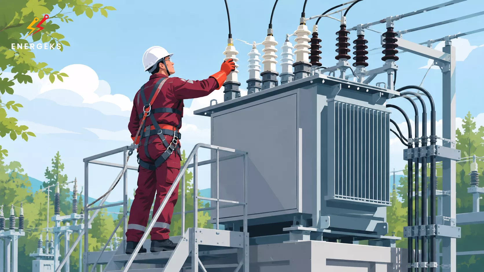
The most common mistakes when installing a transformer concern the foundation, ventilation, service access, earthing, cable routes, protection systems, fire protection, oil retention and environmental conditions. Most of them can be eliminated at the design stage, before the multi‑tonne device arrives on site and politely refuses to cooperate with the prepared space.
A transformer can operate for decades. It cannot, however, move the foundation, widen the doors or persuade cables to suddenly bend according to the designer's wishes.
At Energeks, we have sold hundreds of transformers.
Our devices go, among other things, to projects supporting the infrastructure of Poland's largest distribution system operators, industrial plants and distributed generation installations.
We know that the most expensive corrections often begin with quite innocent statements:
"The room should be sufficient."
"The ventilation will somehow manage."
"The bushing is only slightly offset."
"Service will fit in somehow."
The problem is that centimetres can later turn into hours of downtime, and underestimated temperature, humidity or device weight can shorten the life of an installation designed for many years of operation.
In this article, we will walk through transformer installation from the ground up, literally.
We will start with the foundation and transport conditions, then check ventilation, temperature, humidity, noise and service access.
We will look at earthing, cable routes, bending radii and protection systems.
Finally, we will organise fire protection, oil retention, documentation and acceptance.
This article is for designers, investors, contractors, site managers and maintenance teams. After reading, you will more easily recognise decisions that look good on the drawing but require additional checking before installation.
Because a good transformer installation does not start with the crane.
It starts with a design that remembers that paper will accept anything, but the transformer already has its own dimensions, weight and opinion on ventilation.
Reading time: 11 min
On the plan, everything looks tidy.
The transformer rectangle fits in the room. There is a door. There are walls. The clearances look "roughly right". And here begins the first classic.
A transformer does not need only the footprint of its own enclosure. It needs working space, ventilation space, service space, space for cable bending radii, space for safe access and space for the future.
It is a bit like fitting a large wardrobe into a flat. On the plan, the wardrobe fits perfectly. The problem begins when you need to open the doors, pull out a drawer, walk past it with a vacuum cleaner and still not bang your hip on the edge every morning. In power engineering, that "hip" is service, measurements, thermography, cleaning, terminal inspection, access to the nameplate and the ability to replace a component without dismantling half the station.
Manufacturers' documentation often contains specific requirements regarding distances from ventilation openings, walls or other obstacles. Eaton indicates that the required clearances may vary depending on the transformer construction and should be read from the markings and manufacturer's instructions, and in many ventilated devices, clearances at ventilation openings must be maintained.
An innocent design mistake is when someone leaves space "for the dimensions" but does not leave space "for the device's life". Then it turns out that the thermal imaging camera cannot see the critical point, the doors do not open fully, the cables enter at the wrong angle, and the terminals can only be reached with the expression of someone who has just lost a bet with geometry.
The best design does not only solve the question:
will the transformer fit?
It explains how to plan the installation so that the transformer can be safely placed, connected, commissioned, inspected, serviced and, in the future, also replaced…
And since even the best unit does not work forever, it is worth knowing when it pays to refurbish a transformer and when it is more sensible to replace it with a new one. We have devoted a separate article to this topic, which may interest you, dear reader:
Refurbish or replace? Your transformer's last chance!
A transformer works quietly, but it constantly gives off heat.
No‑load and load losses do not magically disappear into the air. They turn into temperature, and temperature is one of the most patient enemies of insulation.
The most innocent mistake sounds like: "the room is large, so it will be fine."
Not necessarily.
Ventilation in medium‑voltage stations serves primarily to remove heat generated by transformers and other equipment, and to support drying after periods of moisture. At the same time, excessive ventilation can also be a problem, because it can increase the risk of condensation, especially during sudden temperature changes.
MV station ventilation should be maintained at the minimum required level, and ventilation openings should support natural convection, with inlet and outlet arranged so that heat can actually leave the transformer space.
This is important, because many people think of ventilation as a grille in the wall. And the transformer thinks of ventilation as a thermal balance.
If the design does not take into account the transformer's losses, ambient conditions, solar exposure of the enclosure, switchgear operation, possible overload states, local temperature and air flow, the ventilation grille becomes a technical decoration. It looks nice, but does not necessarily do the job.
With dry‑type transformers, the problem is particularly insidious, because the absence of oil can give a false sense of simplicity. Meanwhile, dry transformers also require appropriate cooling conditions, air cleanliness and maintenance of the required clearances. If the openings are obstructed, the air flow path is accidental, and dust accumulates in the room, the device begins to operate in an environment that the designer did not plan, but which designed itself. Only worse.
Good ventilation is not a "bigger hole in the wall". Good ventilation is a conversation between physics, the manufacturer's documentation and the real conditions of the facility.
Humidity is not a small problem.
It is a problem that puts on an invisible suit and works quietly.
In the design, we often see walls, a roof, doors, grilles, a foundation and the equipment layout. We less often see the microclimate.
That is, what happens in the morning when the temperature changes rapidly.
What happens after heavy rainfall.
What happens in winter when the device is temporarily switched off.
What happens near the sea, industrial plants, fields, roads or areas with high dust levels.
Equipment manufacturers point out that air flow should not cause rapid temperature changes leading to the dew point being reached. In practice, this means that "more air" does not always mean "better".
Sometimes it means "more condensation on components that really do not like condensation" – the designer provides ventilation but does not account for moisture behaviour. The station must breathe, but it must not draw problems inside. Ventilation openings, louvres, baffles, the way switchgear is positioned relative to the transformer, anti‑condensation heating and dust protection are not aesthetic details. They are elements of maintaining the working environment.
For outdoor installations, exposure to sun, wind and precipitation also matters. An enclosure heated in summer acts like a metal thermos, only in a less amusing version. In winter, sudden temperature changes can create conditions for condensation, especially when equipment does not operate with a continuous load.
A well‑designed transformer installation does not fight the weather heroically. It anticipates it. That is a calmer and cheaper strategy.
The foundation under a transformer is not a podium.
It is an element of the technical system.
It must carry the weight of the device.
It must maintain level.
It must work with the transport and unloading route.
It must enable drainage, earthing, possible liquid retention, cable routing and access to mounting points.
It must also not crack when theory ends and the crane, jack, rollers, trolley and real pressure begin.
An innocent mistake looks like this: the design assumes a load‑bearing capacity, but does not consider the installation process. Or the substrate is designed for a static state, but transient loads during internal transport are not checked. Or the foundation is strong but has incorrect slopes. Or assembly tolerances are not foreseen, and the transformer ends up positioned so that everything works, but every cable connection requires a small prayer to geometry.
For oil‑immersed transformers, there is also the issue of the oil containment basin, tightness, drainage and control of possible leaks. For dry‑type transformers, the stability of the substrate, the absence of excessive vibration transmission and the cleanliness of the surroundings are important. In both cases, the foundation is the first declaration of the project's quality.
Good practice is to design the foundation not only for "the transformer will stand here", but for the entire scenario: delivery, unloading, movement, positioning, connection, commissioning, inspections, service and replacement.
In power engineering, very often the project that wins is not the one that looks most elegant on the drawing. It is the one that gives the installation team the most common sense on site.
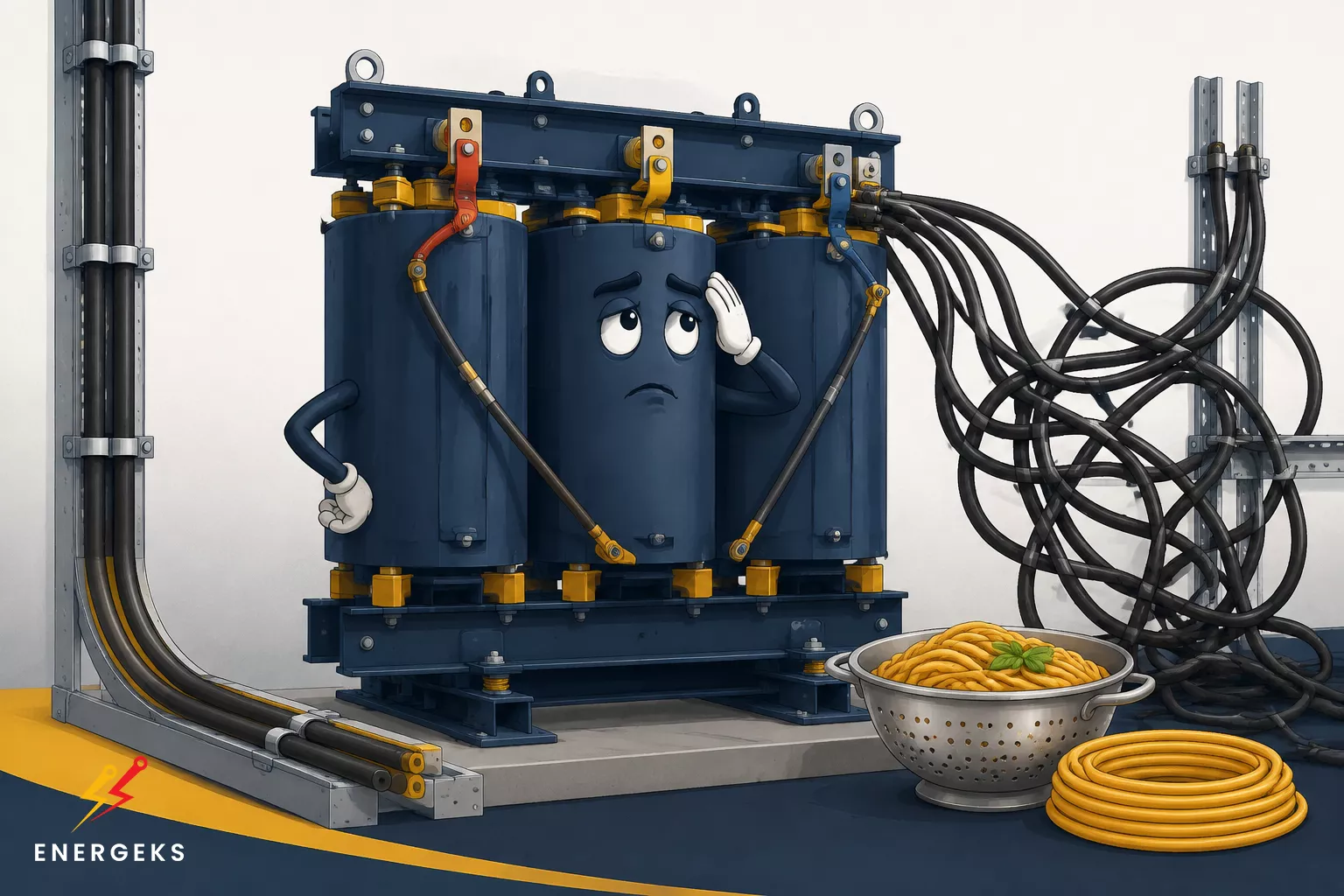
Power cables are not pasta.
They cannot be "laid somehow" without consequences.
One of the most underestimated mistakes is the incorrect positioning of bushings, cable trenches and cable entry points to the transformer. On the drawing, a shift of 20 cm looks innocent.
In reality, it can mean too small a bending radius, stress on cable terminations, difficult installation, a greater risk of connection errors and poor access for inspection.
The transformer manufacturer specifies the permissible cable entry points, the requirements for space inside the enclosure and the method of making connections. Schneider Electric, in its instructions for dry‑type transformers, indicates, among other things, to use the designated entry areas of the enclosure, to use flexible routing where possible, and to use a calibrated torque wrench for electrical connections.
This is not bureaucracy. This is the mechanics of electrical contact.
A connection tightened too much can damage the component. One tightened too little can heat up. A poorly routed cable can work mechanically where it should be calm. A lack of space for laying the conductors can make the installer fight with the material instead of performing precise work.
An innocent design mistake: "we will put the bushing here because it fits nicely against the wall."
A better question is: "will the cable have its natural path, without stress, without struggle and with access for inspection?"
A well‑designed cable route looks a bit like good choreography. Nothing jerks. Nothing strains. Every movement makes sense.
Power cables are not pasta. ;) If their layout starts to resemble an Italian dinner, it is time to go back to the cable route design. CC: ENERGEKS 2026
Earthing is one of those topics where it is not worth being creative in the wrong sense.
Poorly designed earthing and equipotential bonding can cause problems with safety, protection operation, overvoltages, electromagnetic interference and the reliability of the entire installation. Yet in many projects, the topic is treated as the last item on the list: "earth in accordance with the standard."
Only the transformer does not read such mental shortcuts. It works in a specific network system, with a specific short‑circuit impedance, a specific neutral point, specific switchgear, specific fault conditions and specific shock protection.
IEC 61936‑1:2021 concerns the design and execution of power installations above 1 kV AC and indicates requirements to ensure safety and proper operation of the installation according to its intended purpose. This is a good example of systems thinking: the transformer is not a lonely island, but an element of an installation that should behave predictably even under fault conditions.
An innocent mistake is that the design shows an earthing point but does not show the full logic of the connections. It does not analyse the flow of fault currents. It does not take into account compatibility with surge protection. It does not anticipate the quality of equipotential bonding between the transformer enclosure, switchgear, structures, trenches and the earthing busbar.
Good earthing is not a line on a diagram. It is the behaviour of the installation at the worst possible moment.
For oil‑immersed transformers, the topic of fire and environmental protection must enter the design early.
Not when the building is already standing, the distances are fixed, and the investor asks whether "this can somehow be solved".
Transformer oil performs an insulating and cooling function, but in classic mineral solutions it can be a combustible material.
Oil‑immersed transformers are an important element of electrical infrastructure, and the oil used in such devices can pose a fire risk, therefore they require well‑thought‑out protection.
An innocent mistake sounds like: "we will put the transformer here because it is closest to the switchgear."
Closest does not always mean best.
The transformer location should take into account distances from buildings, partitions, escape routes, other equipment, material stores, auxiliary installations and critical infrastructure. For oil‑immersed transformers, oil retention and the ability to contain contaminants in the event of a leak are added.
IEEE Std 980 is a guide for the limitation and control of oil spills in substations, and its purpose includes designing solutions that help contain oil and limit environmental effects.
This is particularly important for photovoltaic farms, energy storage systems, industrial plants and stations where one transformer is not just a device but a node of the entire process. A fire or leak then does not mean only the repair of one component. It can mean downtime, environmental procedures, production loss, delays and difficult conversations with the insurer.
A good transformer location is not the choice of the shortest cable route. It is the choice of the safest working architecture.
A transformer hums. That is normal.
The problem begins when the design assumes that "normal" means "unimportant".
Noise and vibrations can travel through the building structure, cable trenches, rigid connections and sound‑reflecting surfaces. As a result, a transformer that itself meets the requirements can, after installation, become a source of nuisance because the surroundings act like a resonance box.
The transformer location affects the perceived sound level, and installation in a corner, a narrow corridor or near smooth surfaces can cause sound reflection and amplification. Measures to limit vibration transmission are also recommended, for example appropriate insulating pads, flexible cable routing and secure fixing of enclosure panels.
An innocent mistake: "we will put it in the corner, it will be less intrusive."
Sometimes it is precisely in the corner that it is more intrusive.
If the transformer is located near offices, control rooms, dwellings, property boundaries or people's workplaces, the acoustics topic should appear before installation. And it is not about dramatising. It is about respect for user comfort and avoiding costly corrections that later resemble treating a toothache by changing the chair.
Noise is designed with space. Vibrations are designed with detail. And operational peace is designed earlier, not after the first complaint.
The transformer is patient, but it is not alone.
It works with the MV switchgear, the LV switchgear, protection devices, surge arresters, the metering system, automation, loads and the load character.
A design mistake looks innocent when each element "by itself" is correct. The protection is selected. The instrument transformers are selected. The cables are selected. The switchgear is selected. Only then it turns out that together they do not play like an orchestra, but like five people tuning instruments in a lift.
Protection coordination should take into account short‑circuit currents, transformer inrush current, selectivity, permissible overloads, the nature of the loads, the presence of inverters, energy storage systems, reactive power compensation, automation systems and the grid operator's requirements. In modern installations with photovoltaics, electric vehicle chargers and energy storage systems, the load is no longer a simple story of motors and lighting. It is a dynamic ecosystem.
This is the essence: transformer installation does not end with the transformer.
If the protection devices are designed without a conversation with the entire installation, they can act too nervously, too late or in the wrong place. And then even a very good transformer is drawn into problems it did not create.
Technical acceptance should not be a finale full of surprises.
It should be a confirmation of what the design foresaw from the beginning.
An innocent mistake: the documentation assumes installation but does not assume proper commissioning. There is no clear list of measurements. There is no provision for access to inspection points. The sequence of activities is not planned. It is not clear who is responsible for checking settings, who for tests, who for as‑built documentation, who for compliance with the DTR, and who for the decision to energise.
Eaton, in its material on best practices for dry‑type transformers, indicates that new transformers should be inspected on receipt for transport damage, and before energisation, among other things, auxiliary devices, tap selection, ratio connections, and the tightening and clearances of electrical connections should be verified.
This sounds simple. And that is precisely why it is sometimes omitted.
Transformer commissioning is not a ribbon‑cutting. It is the moment when the design, delivery, installation, measurements, protection and operation meet at one point. If everyone worked in separate silos before, commissioning will show it.
In a good design, at the documentation stage, it is already known what measurements will be needed, what conditions must be met, what protocols will be produced and which elements must be checked before voltage is applied. Thanks to this, commissioning is a calm process, not a technical escape room with a clock in the background.
The cheapest time to foresee expansion is before construction.
After that, every additional metre, every bushing, every space reserve and every change to the cable route starts to cost more, because it conflicts with operating infrastructure.
In transformer projects, this mistake appears often. Today one transformer is enough. Today a given power is enough. Today there is no energy storage system. Today there are no chargers. Today the photovoltaic farm has a specific layout. Today the plant operates on its current load profile.
But the power industry is changing faster than before. Companies are electrifying processes. Electric vehicle charging stations are being added. Requirements for power quality are increasing. Energy storage systems, inverters, compensation, automation, monitoring and new operating models are appearing.
An innocent design mistake is that the installation is designed perfectly for today, but without a margin for tomorrow.
It is not always about oversizing the transformer. Sometimes it is about space reserve, an additional bushing, a sensibly planned station layout, the ability to add apparatus, a cable route without traps and an architecture that does not close the door on the investor.
A good design does not predict the future. It leaves reasonable space for it.
The best strategy is simple, though it requires discipline: design the transformer as part of the system, not as a device to be placed.
First, data must be collected.
Power, transformer type, losses, weight, dimensions, manufacturer's requirements, environmental conditions, service access, short‑circuit parameters, network configuration, load profile, operator requirements, expansion scenario and site constraints.
Then geometry must be checked.
Not only the footprint, but also access, door opening, cable routes, bending radii, trenches, bushings, grilles, service zones, crane or transport equipment access, and the possibility of replacing the device in the future.
Then heat must be calculated.
The transformer dissipates losses to the surroundings, so ventilation must be matched to the real conditions. It must be neither symbolic nor excessive. It should operate stably, without creating condensation problems.
The next step is safety.
Earthing, equipotential bonding, shock protection, protection devices, fire protection, oil retention, escape routes and access for emergency services cannot be an add‑on at the end.
Finally, documentation.
Manufacturer's instructions, protocols, measurements, settings, diagrams and as‑built documentation should be prepared so that operation does not have to guess what the designer meant.
A good transformer installation design has something very elegant about it: it does not shout.
It just works.
Transformer installation is not a stage that begins on the day of delivery.
The most innocent installation mistakes have a common feature: at the beginning they save a few minutes, and later they can take a few weeks. That is why it is worth, early enough, comparing the design with the manufacturer's documentation, the technical requirements, the site conditions and the planned method of operation.
The transformer really does not expect luxuries.
It needs a stable base, an adequate amount of air, good connections, well‑thought‑out protection and a little respect for physics. In return, it can reliably perform its work for many years.
Thank you for staying with us to the end.
Hundreds of transformers sold and participation in projects powering Poland's energy infrastructure confirm that good solutions start with proper selection and technical partnership.
Explore Energeks transformers, check the units available in stock, and join Energeks on LinkedIn, where we share technical knowledge, projects and what is currently happening in the power industry!
References:
Schneider Electric, Electrical Installation Guide (Schneider Electric)
Eaton, Best practices for the installation and inspection of dry type distribution and power transformers . (Eaton)
Shipped from our warehouse in Poland within 2–3 working days, 5-year warranty. Full range 25–2500 kVA in the shop (prices in PLN).
No reviews!