Transformer substations
Compact transformer substation with outdoor operation up to 1250 kVA
Where it is used and how it is built
Applications
- retail and services
- farms and food processing
- residential buildings and housing estates
- small plants and workshops
- substations handed over to a DSO whose standard specifies external operation
Design
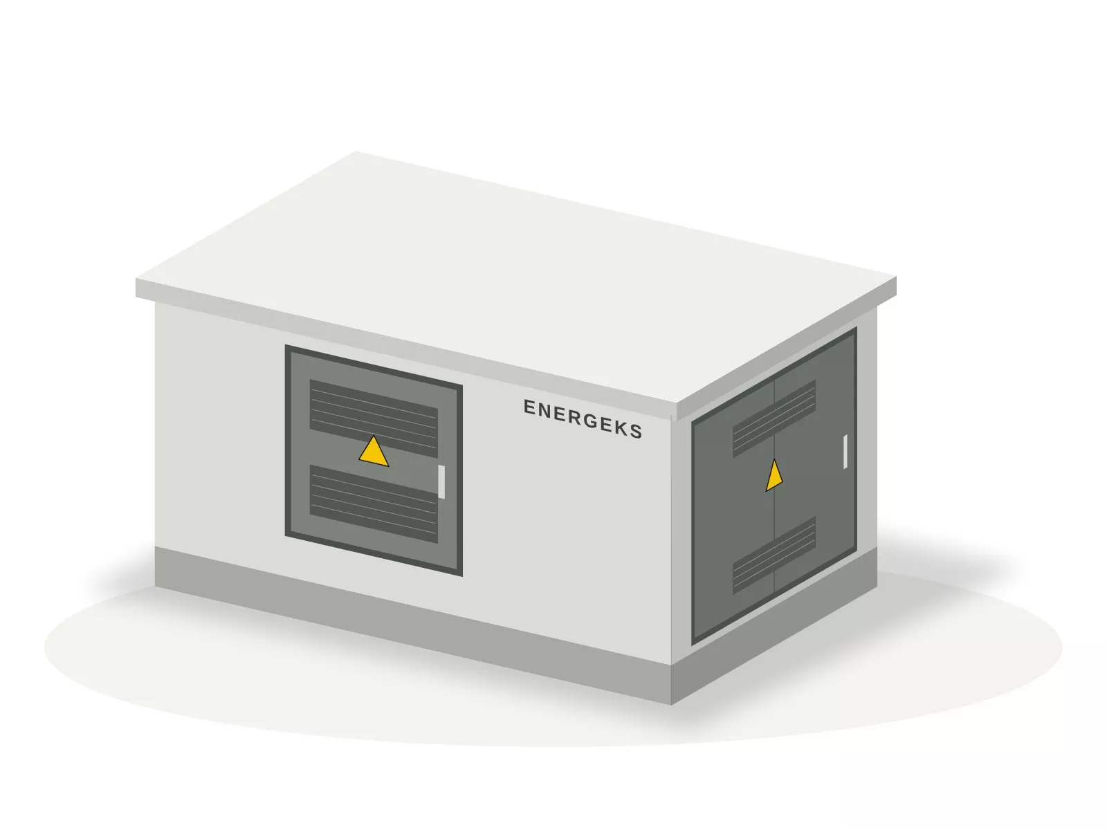
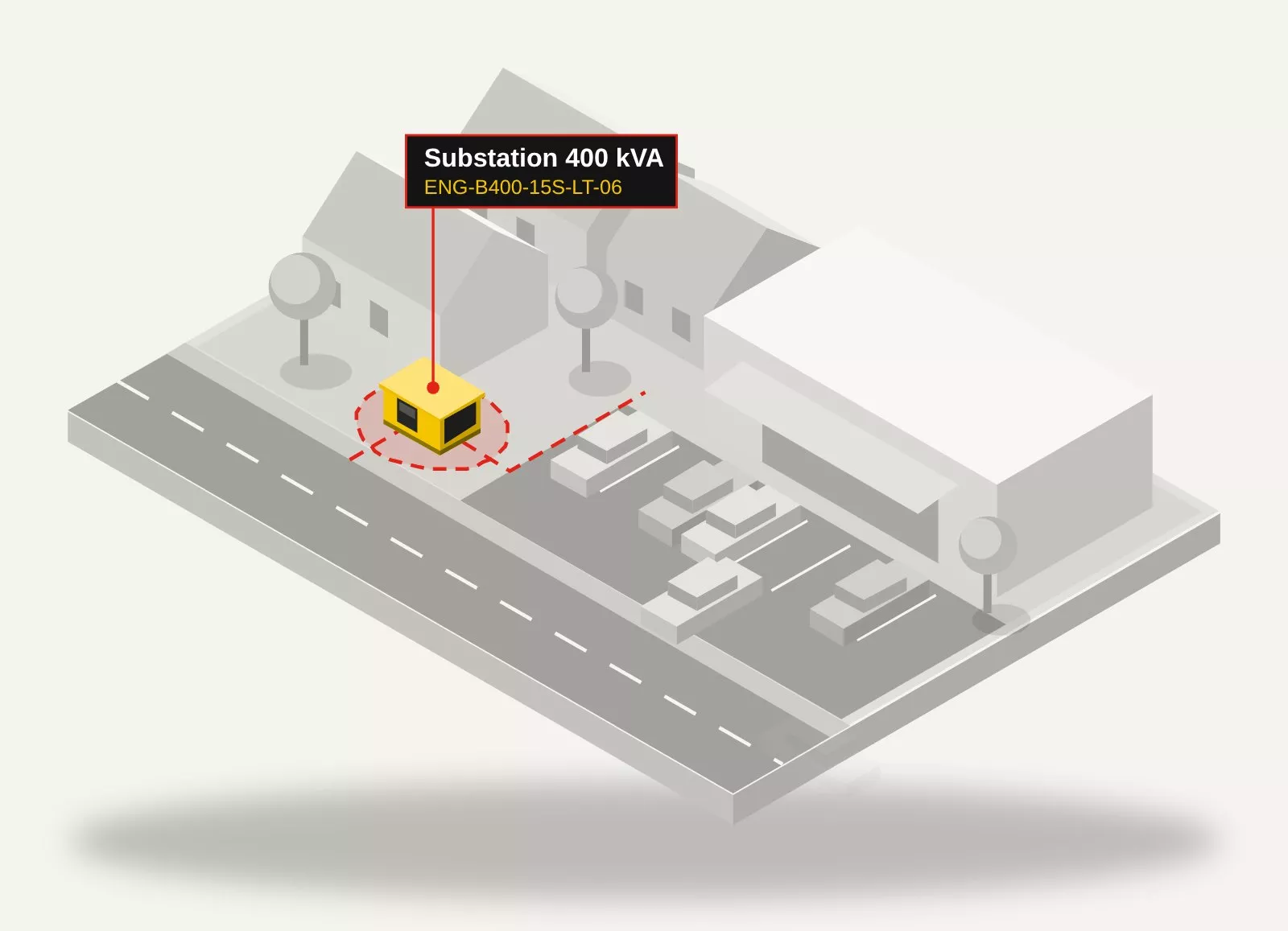
- Compact enclosure 2.90 x 1.60 m: transformer up to 250 kVA, 2 MV panels, up to 6 LV outgoing feeders including spares.
- Compact enclosure 2.90 x 2.10 m: transformer up to 630 kVA, up to 5 MV panels and 15 LV outgoing feeders; in the REI 120 version up to 4 MV panels and 10 outgoing feeders.
- Compact monoblock: height 2.46 m, approx. 1.70 m above ground, buried depth approx. 0.77 m on a 0.10 m bedding layer.
- Widened 2.96 m enclosures up to 1250 kVA: transformer chambers in the middle, LV compartment at one end wall, MV compartment at the other, each with an external door; foundation with cable basement.
- Oil sump for the full oil volume, natural ventilation, anti-condensation heating, door interlocks for the transformer chamber and the MV switchgear.
Advantages
- Small footprint: 4.64 m² or 6.09 m² with a compact enclosure.
- Lighter transport and a smaller crane: the compact enclosure weighs approx. 7.5 or 9.6 t (without equipment).
- Quicker placement: monoblock with base on a bedding layer, no separate foundation.
- Layout in line with the expectations of operators who take over substations with external operation.
Limitations
- Switching and meter readings with the doors open, including in rain and in winter.
- Less space for equipment: up to 5 MV panels and 15 LV outgoing feeders in a compact enclosure.
- Above 1250 kVA and for two transformers above 630 kVA, only an enclosure with an operating corridor.
Typical configurations and substation codes
| Rating | Substation code | Enclosure | Enclosure weight | MV panels | Metering | LV main device | LV outgoing feeders |
|---|---|---|---|---|---|---|---|
| 100 kVA | ENG-B100-15S-LT-04-N1 | KSZ 2.90 x 1.60 m | approx. 7.5 t | L+T, HH 10 A | LV, 150/5 A | switch-disconnector 250 A | 4 x NH1 250 A |
| 160 kVA | ENG-B160-15S-LT-04 | KSZ 2.90 x 1.60 m | approx. 7.5 t | L+T, HH 16 A | LV, 250/5 A | switch-disconnector 400 A | 4 x NH2 400 A |
| 250 kVA | ENG-B250-15S-LT-04 ready set | KSZ 2.90 x 1.60 m | approx. 7.5 t | L+T, HH 25 A | LV, 400/5 A | switch-disconnector 630 A | 4 x NH2 400 A |
| 400 kVA | ENG-B400-15S-LPT-06 | KSZ 2.90 x 2.10 m | approx. 9.6 t | L+P+T, HH 31.5 A | MV, 20/5 A | switch-disconnector 800 A | 6 x NH2 400 A |
| 400 kVA | ENG-B400-15S-LT-06 ready set | KSZ 2.90 x 2.10 m | approx. 9.6 t | L+T, HH 31.5 A | LV, 600/5 A | switch-disconnector 800 A | 6 x NH2 400 A |
| 630 kVA | ENG-B630-15S-LPT-06 ready set | KSZ 2.90 x 2.10 m | approx. 9.6 t | L+P+T, HH 40 A | MV, 25/5 A | switch-disconnector 1250 A | 6 x NH2 400 A |
| 800 kVA | ENG-B800-15S-LPT-08 | KSWz 2.96 x 3.96 m | approx. 25.1 t | L+P+T, HH 50 A | MV, 40/5 A | air circuit breaker 1250 A, Icu min. 20 kA | 8 x NH2 400 A |
| 1000 kVA | ENG-B1000-15S-LPV-08 | KSWz 2.96 x 3.96 m | approx. 25.1 t | L+P+V, circuit breaker | MV, 40/5 A | air circuit breaker 1600 A, Icu min. 24 kA | 8 x NH2 400 A |
| 1250 kVA | ENG-B1250-15S-LPV-10 | KSWz 2.96 x 3.96 m | approx. 25.1 t | L+P+V, circuit breaker | MV, 50/5 A | air circuit breaker 2000 A, Icu min. 30 kA | 10 x NH2 400 A |
| 2 x 400 kVA | ENG-B2x400-15S-LPTT-06 | KSWz 2.96 x 5.36 m | approx. 32 t | L+P+T+T, HH 31.5 A | MV, 40/5 A | 2 x switch-disconnector 800 A | 6 x NH2 400 A per section |
| 2 x 630 kVA | ENG-B2x630-15S-LPTT-06 | KSWz 2.96 x 5.36 m | approx. 32 t | L+P+T+T, HH 40 A | MV, 50/5 A | 2 x switch-disconnector 1250 A | 6 x NH2 400 A per section |
Values from the Energeks station configurator for a 15 kV network and MV switchgear with solid and air insulation. Enclosure weights are indicative, without equipment and transformer. Click a code to open the configuration in the configurator.
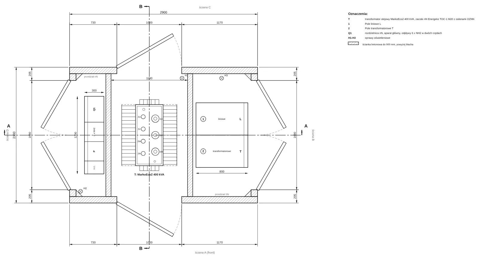
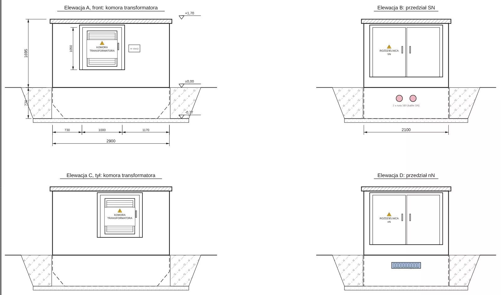
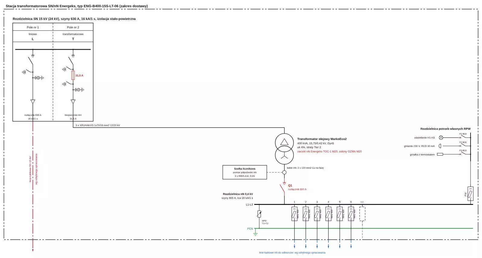
Plan, elevations and single-line diagram
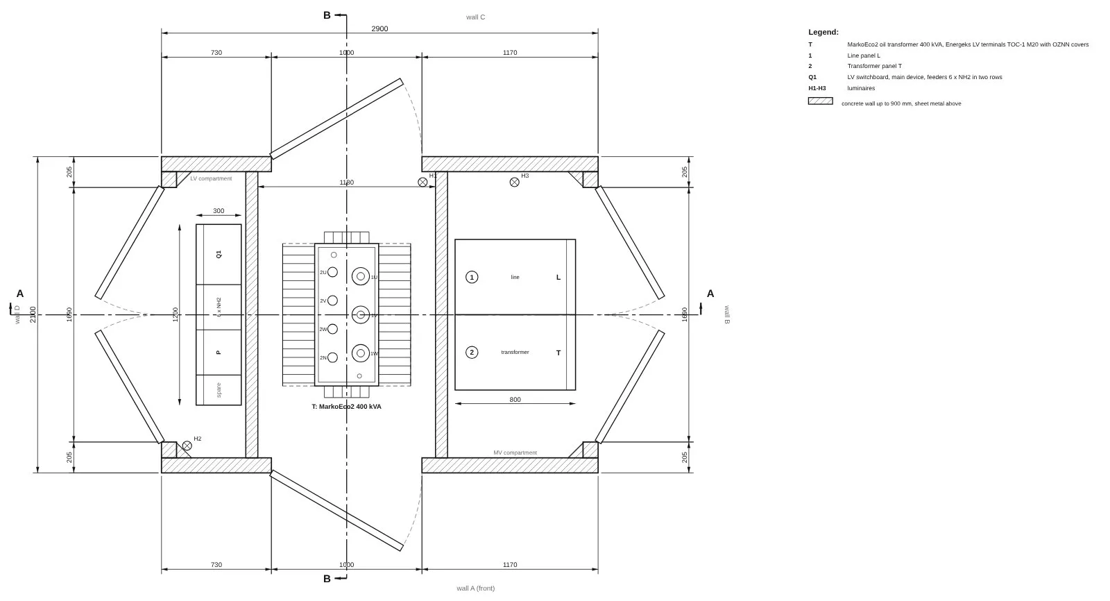
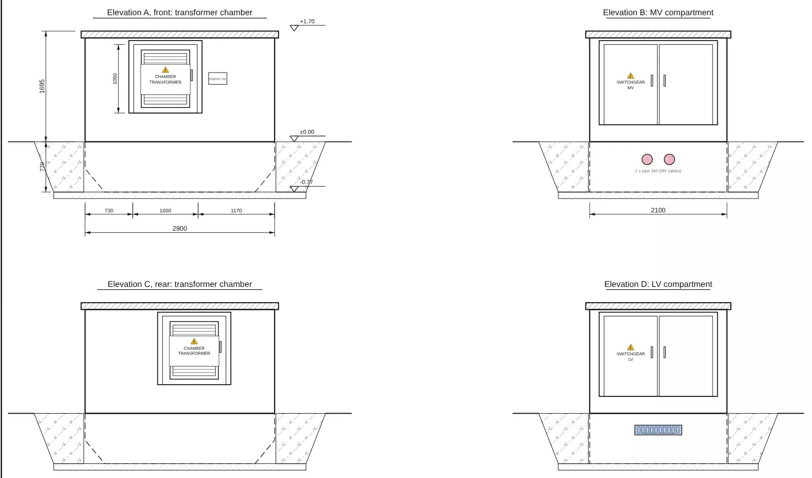
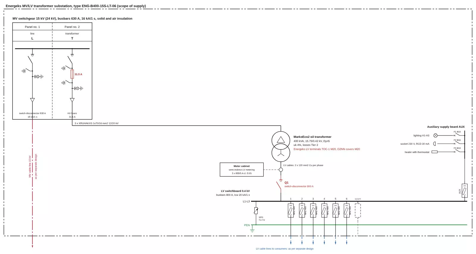
Drawings of a sample configuration from the station configurator. The full drawing set for any configuration can be downloaded in the configurator without registration (in Polish).
Clamps and covers on the transformer
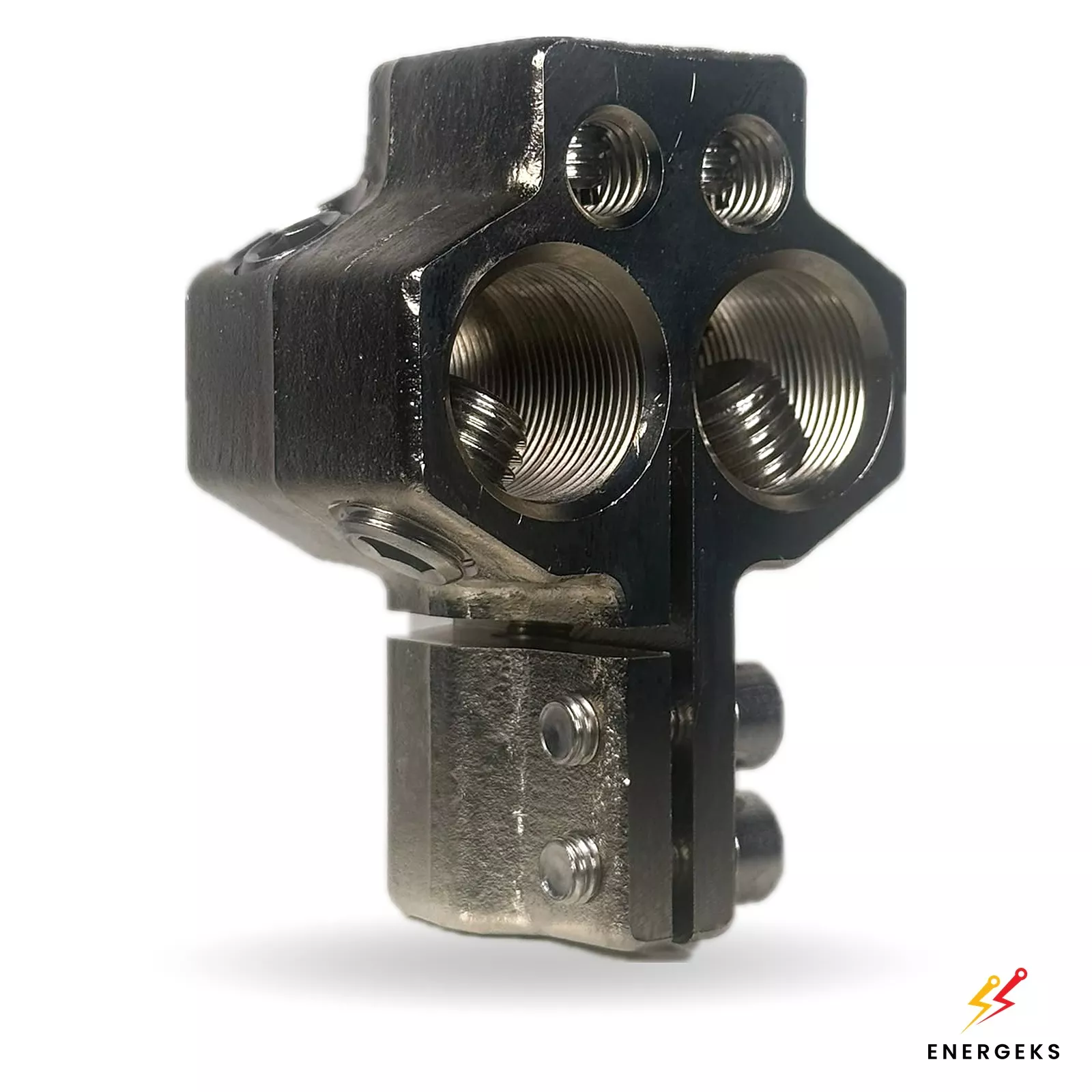
TOC-1 LV clamps
Standard in substations up to 630 kVA: horizontal, lugless, set of 3 x /U and 1 x /N; M12, M20 or M30 selected to suit the rating.
View product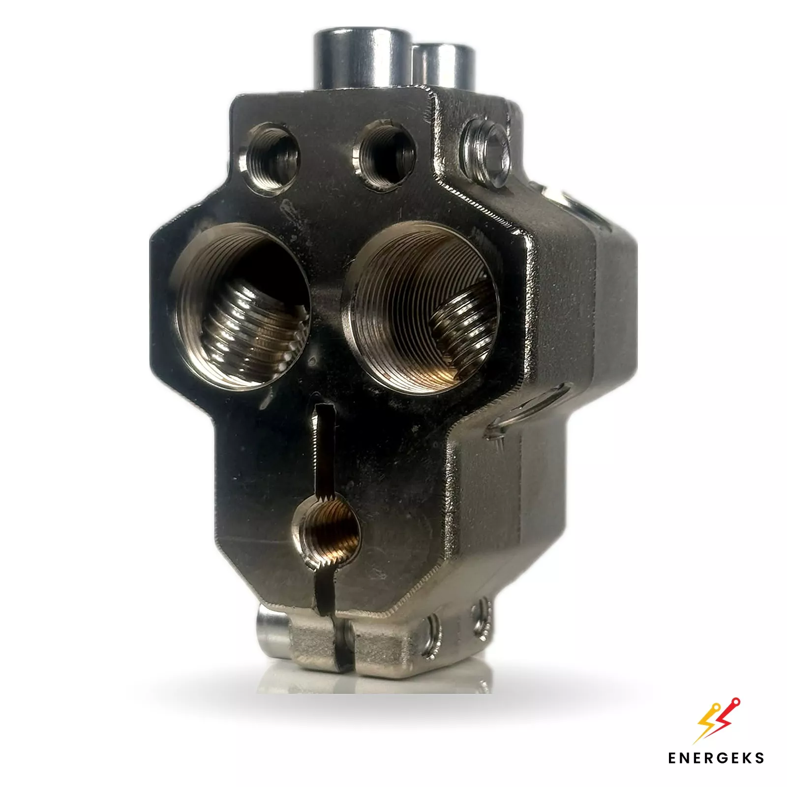
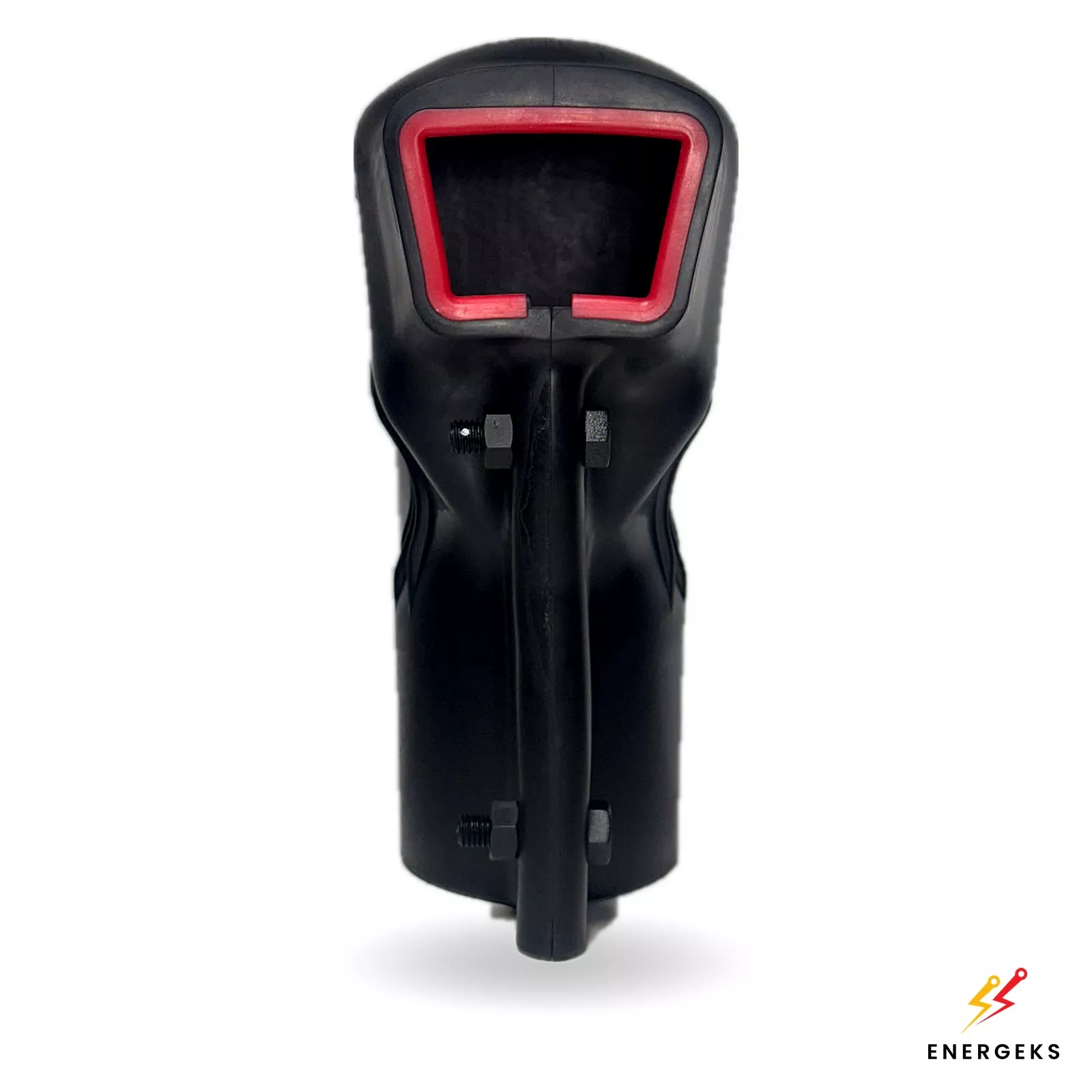
OZNN covers
4 insulating covers for LV clamps made of flexible self-extinguishing plastic, fitted after the cables are connected.
View productFrom substation code to quotation
Choose a type
A substation type or a ready set with a configuration that recurs most often in projects.
Adjust in the configurator
Rating, voltage, MV panels, metering, feeders and options; each configuration gets a substation code.
Download documents
Technical design, data sheet, single-line diagram, drawings and bill of materials, no login.
Request a quote
Send the substation code, location and date. Price on request.
One supplier for substation and transformer
SF6-free MV switchgear
Solid and air insulation, air insulation or a gas with GWP below 1. In line with EU Regulation 2024/573.
MarkoEco2 transformer
Hermetically sealed oil-immersed, losses to Ecodesign Tier 2, 60-month warranty. Cast resin TeoEco2 on request.
Documentation at once
Technical design for adaptation by your designer, data sheet, drawings and bill of materials from the configurator, no registration.
18 weeks with transport
Standard lead time of 18 weeks from order, transport to the site specified by the customer.
Open the configurator (The configurator and the shop are in Polish; documents can be downloaded without registration.)
Ask about the product
Fill out the form below and contact us.
Our advisors will respond as soon as possible.