Transformer substations
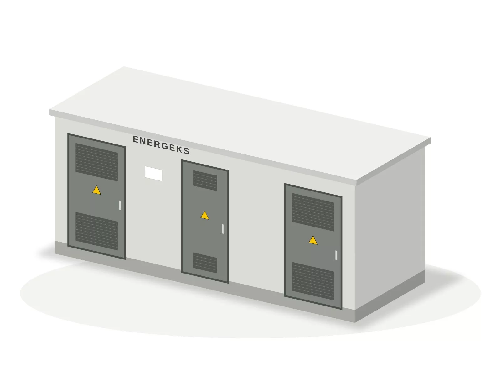
EV charging transformer substation 630 to 2500 kVA
Where it is used and how it is built
Applications
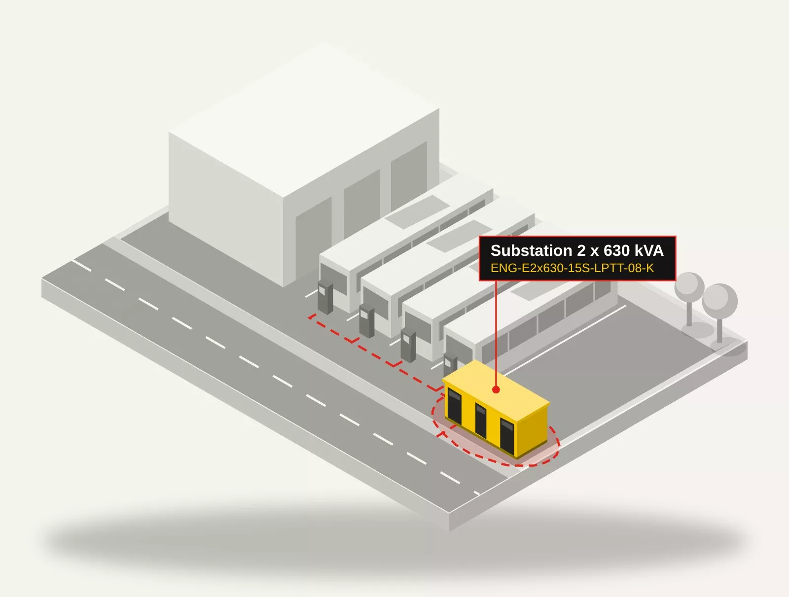
- electric bus depots
- roadside charging hubs
- delivery fleets and logistics bases
- company and retail car parks
Design
- Enclosure with operating corridor, width 2.55 m (630 kVA, 2 x 630 kVA) or 2.96 m (800 to 1250 kVA, 2 x 800 and 2 x 1000 kVA); from 1600 kVA a custom multi-segment enclosure.
- Transformer panel with switch-disconnector and HH fuses up to 800 kVA, with circuit breaker from 1000 kVA (15 kV network); billing metering on the MV side in the metering panel.
- LV switchboard for 4 to 16 NH outgoing feeders (up to 24 panels including spares), with two transformers two sections with a normally open bus coupler, type 1+2 surge arresters.
- From 800 kVA the LV main device is an air circuit breaker; from 1600 kVA the transformer is connected to the LV switchboard by busbar trunking.
- Telecontrol: provision (T1), FPI short-circuit indicators (T2) or remote control (T3); on request, network analyser, no-load loss compensation and fire brigade switch.
Advantages
- Each charger on its own protected outgoing feeder.
- Two transformers and two LV sections: servicing one transformer does not shut down the entire depot.
- Target rating: enclosure, oil sump, busbars and LV connections sized from the outset for a larger transformer.
- Network analyser on request: technical metering in the LV switchboard.
Limitations
- Chargers introduce higher harmonics: the designer selects the transformer and protection with a margin.
- From 1600 kVA a custom enclosure, without construction drawings in the product range.
- A high connection capacity means MV-side metering and DSO approvals handled by the investor.
Typical configurations and substation codes
| Rating | Substation code | Enclosure | Enclosure weight | MV panels | Metering | LV main device | LV outgoing feeders |
|---|---|---|---|---|---|---|---|
| 630 kVA | ENG-E630-15S-LPT-08-KT1 | KSW 2.55 x 4.00 m | approx. 20.7 t | L+P+T, HH 40 A | MV, 25/5 A | switch-disconnector 1250 A | 8 x NH2 400 A |
| 800 kVA | ENG-E800-15S-LPT-10-KT1 | KSW 2.96 x 4.56 m | approx. 28 t | L+P+T, HH 50 A | MV, 40/5 A | air circuit breaker 1250 A, Icu min. 20 kA | 10 x NH2 400 A |
| 1000 kVA | ENG-E1000-15S-LPV-10-KT1 ready set | KSW 2.96 x 4.56 m | approx. 28 t | L+P+V, circuit breaker | MV, 40/5 A | air circuit breaker 1600 A, Icu min. 24 kA | 10 x NH2 400 A |
| 1250 kVA | ENG-E1250-15S-LPV-12-KT1 | KSW 2.96 x 4.56 m | approx. 28 t | L+P+V, circuit breaker | MV, 50/5 A | air circuit breaker 2000 A, Icu min. 30 kA | 12 x NH2 400 A |
| 1600 kVA | ENG-E1600-15S-LPV-12-KT1 | custom, multi-segment | per design | L+P+V, circuit breaker | MV, 75/5 A | air circuit breaker 2500 A, Icu min. 39 kA | 12 x NH2 400 A |
| 2000 kVA | ENG-E2000-15S-LPV-16-KT1 | custom, multi-segment | per design | L+P+V, circuit breaker | MV, 100/5 A | air circuit breaker 3200 A, Icu min. 48 kA | 16 x NH2 400 A |
| 2500 kVA | ENG-E2500-15S-LPV-16-KT1 | custom, multi-segment | per design | L+P+V, circuit breaker | MV, 100/5 A | air circuit breaker 4000 A, Icu min. 60 kA | 16 x NH2 400 A |
| 2 x 630 kVA | ENG-E2x630-15S-LPTT-08-KT1 | KSW 2.55 x 6.00 m | approx. 29.4 t | L+P+T+T, HH 40 A | MV, 50/5 A | 2 x switch-disconnector 1250 A | 8 x NH2 400 A per section |
| 2 x 630 kVA | ENG-E2x630-15S-LPTT-08-K ready set | KSW 2.55 x 6.00 m | approx. 29.4 t | L+P+T+T, HH 40 A | MV, 50/5 A | 2 x switch-disconnector 1250 A | 8 x NH2 400 A per section |
| 2 x 800 kVA | ENG-E2x800-15S-LPTT-10-KT1 | KSW 2.96 x 6.96 m | approx. 40.1 t | L+P+T+T, HH 50 A | MV, 75/5 A | 2 x air circuit breaker 1250 A, Icu min. 20 kA | 10 x NH2 400 A per section |
| 2 x 1000 kVA | ENG-E2x1000-15S-LPVV-10-KT1 | KSW 2.96 x 7.16 m | approx. 42.5 t | L+P+V+V, circuit breaker | MV, 100/5 A | 2 x air circuit breaker 1600 A, Icu min. 24 kA | 10 x NH2 400 A per section |
Values from the Energeks station configurator for a 15 kV network and MV switchgear with solid and air insulation. Enclosure weights are indicative, without equipment and transformer. Click a code to open the configuration in the configurator.
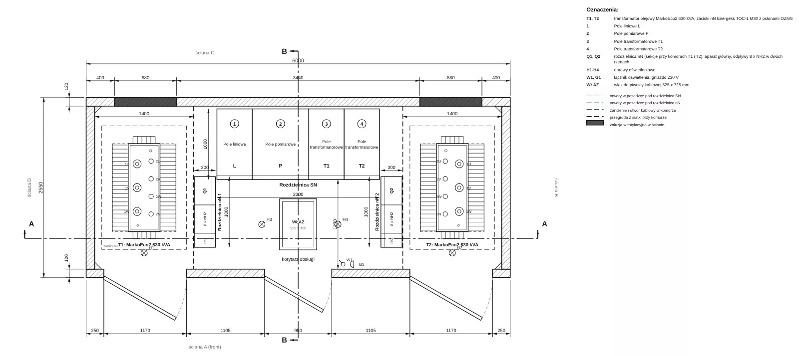
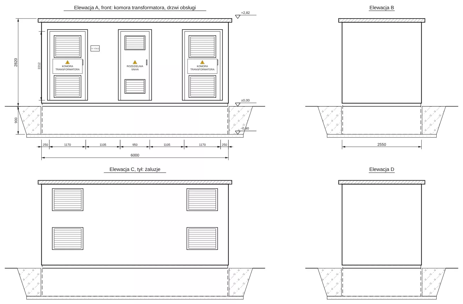
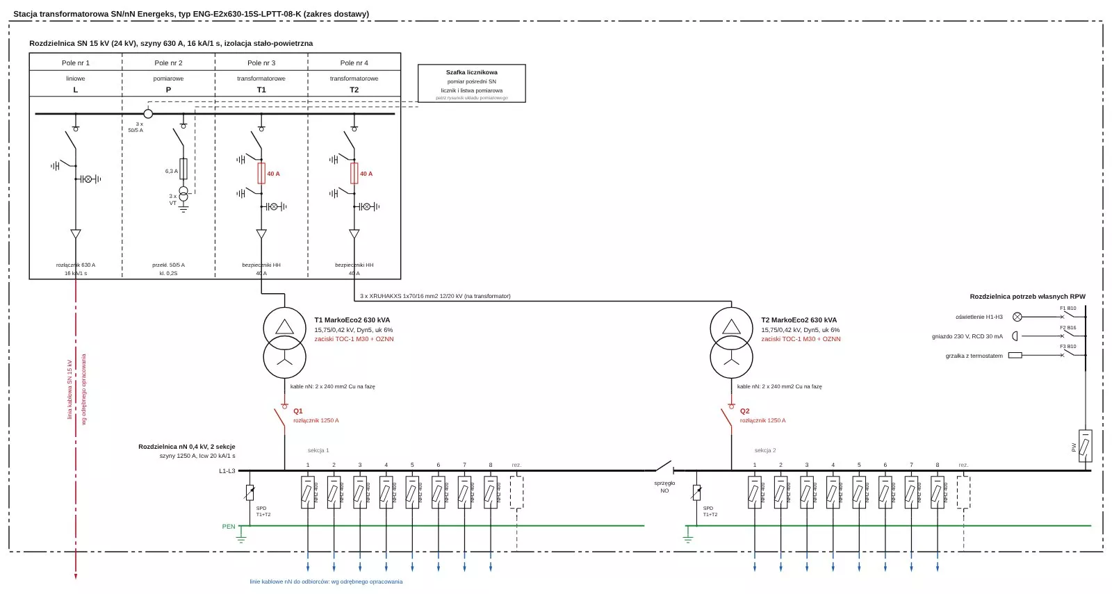
Plan, elevations and single-line diagram
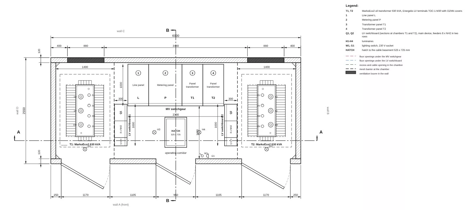
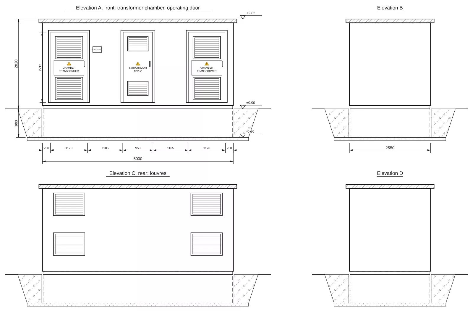
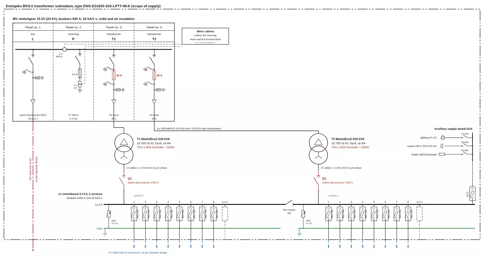
Drawings of a sample configuration from the station configurator. The full drawing set for any configuration can be downloaded in the configurator without registration (in Polish).
Clamps and covers on the transformer
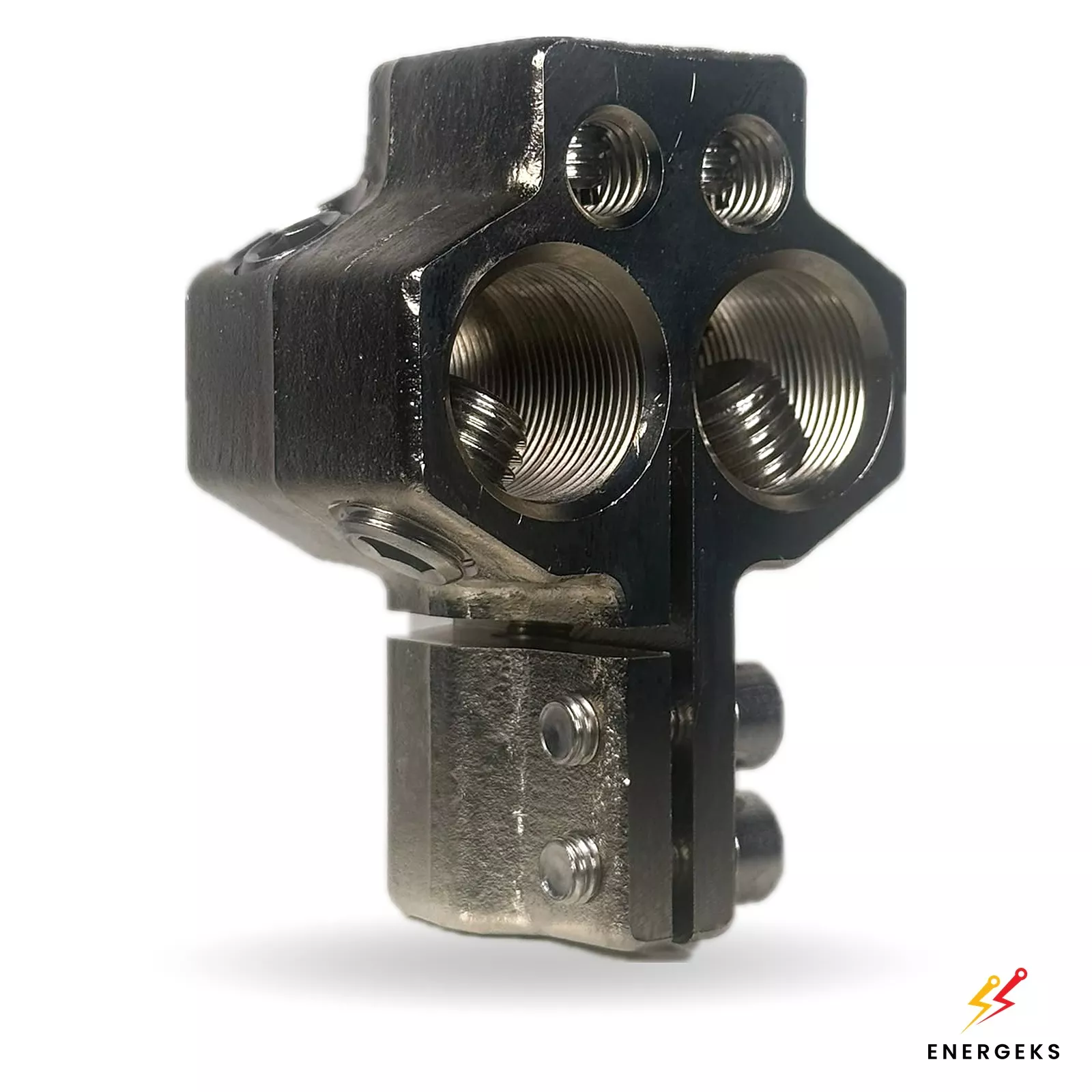
TOC-1 LV clamps
Standard in substations up to 630 kVA: horizontal, lugless, set of 3 x /U and 1 x /N; M12, M20 or M30 selected to suit the rating.
View product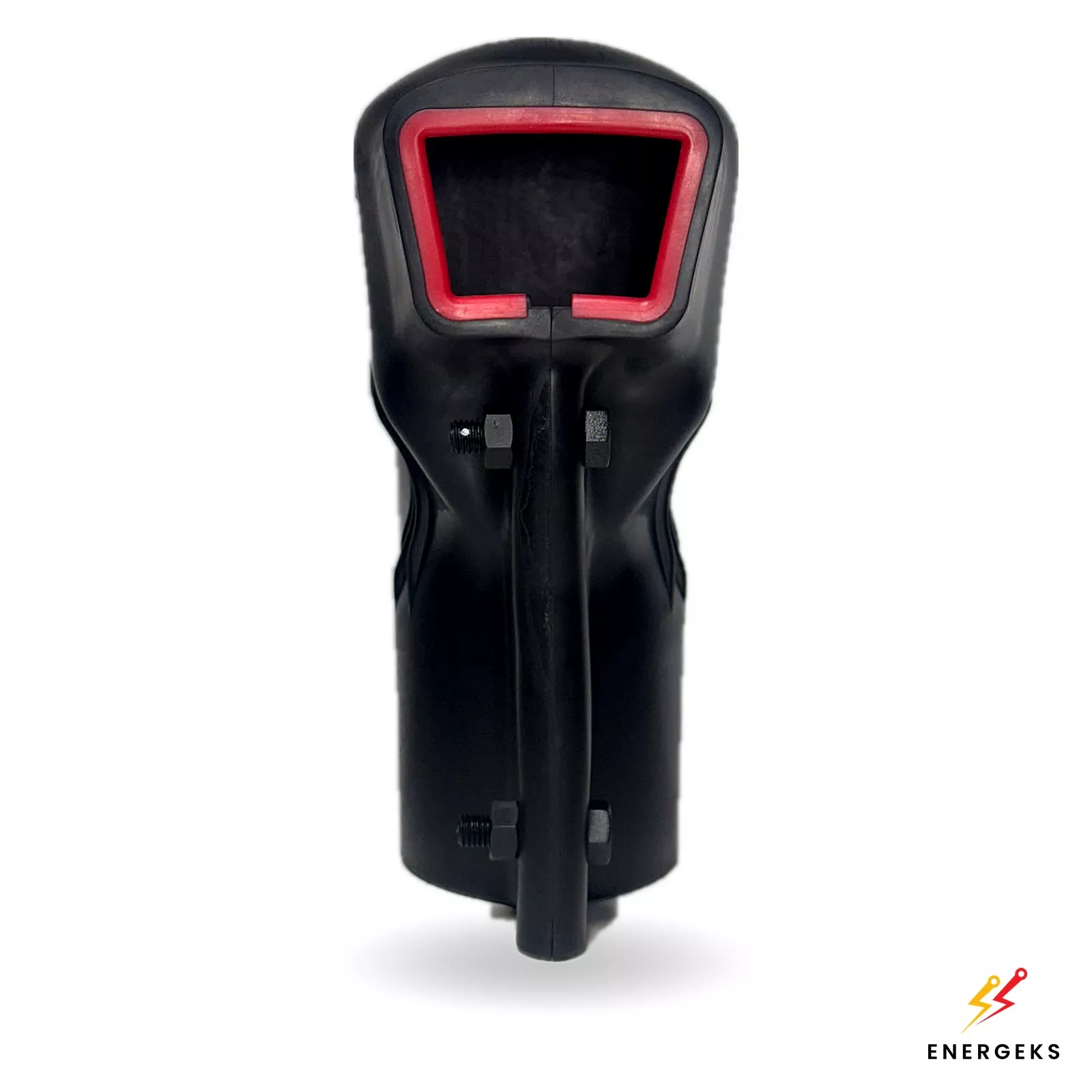
OZNN covers
4 insulating covers for LV clamps made of flexible self-extinguishing plastic, fitted after the cables are connected.
View productMK 5 flat clamps
For a future rating from 800 kVA, when the LV connection has 3 or more cables per phase.
From substation code to quotation
Choose a type
A substation type or a ready set with a configuration that recurs most often in projects.
Adjust in the configurator
Rating, voltage, MV panels, metering, feeders and options; each configuration gets a substation code.
Download documents
Technical design, data sheet, single-line diagram, drawings and bill of materials, no login.
Request a quote
Send the substation code, location and date. Price on request.
One supplier for substation and transformer
SF6-free MV switchgear
Solid and air insulation, air insulation or a gas with GWP below 1. In line with EU Regulation 2024/573.
MarkoEco2 transformer
Hermetically sealed oil-immersed, losses to Ecodesign Tier 2, 60-month warranty. Cast resin TeoEco2 on request.
Documentation at once
Technical design for adaptation by your designer, data sheet, drawings and bill of materials from the configurator, no registration.
18 weeks with transport
Standard lead time of 18 weeks from order, transport to the site specified by the customer.
Open the configurator (The configurator and the shop are in Polish; documents can be downloaded without registration.)
Ask about the product
Fill out the form below and contact us.
Our advisors will respond as soon as possible.