10 Sep
2026
Energeks

A transformer clamp is a small part that carries the full LV current – on a 630 kVA transformer that is over 900 A per phase. If it is the wrong size, it overheats, works loose and can eventually damage the bushing. Choosing one comes down to four questions: what current flows on the LV side, what thread the bushing stud has, how many conductors you connect, and whether the clamp sits on a phase or on the neutral.
The rated current on the low-voltage side follows from the transformer's rated power:
I = S / (√3 × U)
S is the rated power in VA (kVA × 1000) and U the rated LV voltage – usually 400 V or 420 V for distribution transformers. Example for 400 kVA at 420 V: 400,000 / (1.732 × 420) ≈ 550 A.
The clamp screws directly onto the bushing stud, so its internal thread must match the stud. LV bushings of oil-immersed transformers are made to EN 50386, and the stud diameter grows with the bushing current. On distribution transformers up to 630 kVA you will mostly find three sizes:
| Transformer rating | LV current at 400 V | LV current at 420 V | Stud thread | Clamp rating |
|---|---|---|---|---|
| 63 kVA | 91 A | 87 A | M12 | 250 A |
| 100 kVA | 144 A | 138 A | M12 | 250 A |
| 160 kVA | 231 A | 220 A | M12 | 250 A |
| 250 kVA | 361 A | 344 A | M20 | 630 A |
| 400 kVA | 577 A | 550 A | M20 | 630 A |
| 630 kVA | 909 A | 866 A | M30 | 1000 A |
The table shows the typical case, but manufacturers do not always follow it – so we always check the thread on the stud itself or in the transformer documentation (datasheet, dimension drawing). Above 630 kVA the current exceeds 1000 A and larger studs or busbar connections are used – that calls for an individual selection.
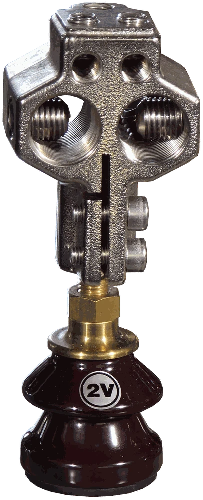
TOC-1 clamp screwed onto the LV bushing stud of a MarkoEco2 transformer.
Horizontal clamps take two main and two auxiliary conductors per phase. For TOC clamps that means:
Conductor codes: RE – solid round, RM – stranded round, SM – stranded sector-shaped. The conductors go straight into the sockets and are clamped by screws, with no crimped cable lugs. Grid operators see it the same way – the Polish DSO TAURON Dystrybucja, in its standard for MV/LV transformers, specifies LV clamps for direct conductor connection without crimped lugs, in a cable or a busbar version.
Cable size and number are the designer's call – based on current-carrying capacity, installation method, voltage drop and short-circuit conditions. The clamp has to physically accept them. If you need more than two main cables per phase, or the transformer is connected to the LV switchgear by busbars, choose a busbar clamp. See our overview of types of transformer clamps.
One transformer needs a set of four clamps: three for the phases and one for the neutral. In the TOC series, /U is the phase clamp and /N has an extra stud (two on TOC-2/N) for the neutral or earthing conductor or an earthing strip. Some operators require that a 25 × 4 mm earthing strip can be connected to the neutral clamp – Energa-Operator's requirements for MV/LV transformers are one example. TOC clamps in the /N version allow this.
Both clamps share the same thread, current rating and connection capacity – they differ in shape and in how much room they take on the tank cover.
| TOC-1 | TOC-2 | |
|---|---|---|
| Design | body with offset foot, two locking screws under the head | compact head, slotted stem, locking screws on the side |
| When to choose | thick cables, easy access to the sockets | LV bushings close together, little room on the cover |
| Catalogue no. | DP 5100–5300, DP 5100N–5300N | DP 6100–6300, DP 6100N–6300N |
Product pages: TOC-1 transformer clamp and TOC-2 transformer clamp.
The full range is in our transformer clamps category. We ship clamps from stock in Poland – separately or fitted to a MarkoEco2 transformer before dispatch. How to install a clamp so that it does not overheat is explained in why transformer clamps overheat.
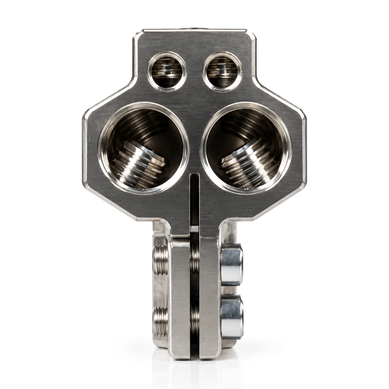 TOC-1 – horizontalM12 / M20 / M30, 250–1000 A, 2 × 300 mm²
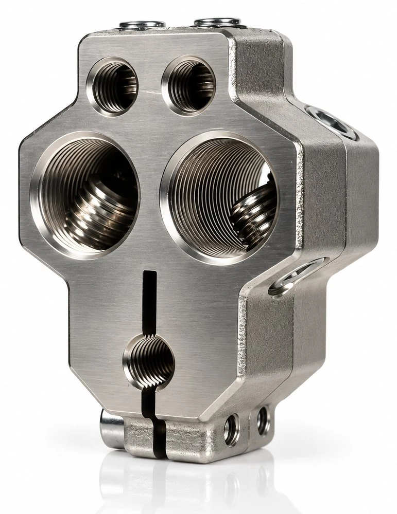 TOC-2 – compactsame connection capacity, smaller footprint
No reviews!