13 Jul
2026
Energeks
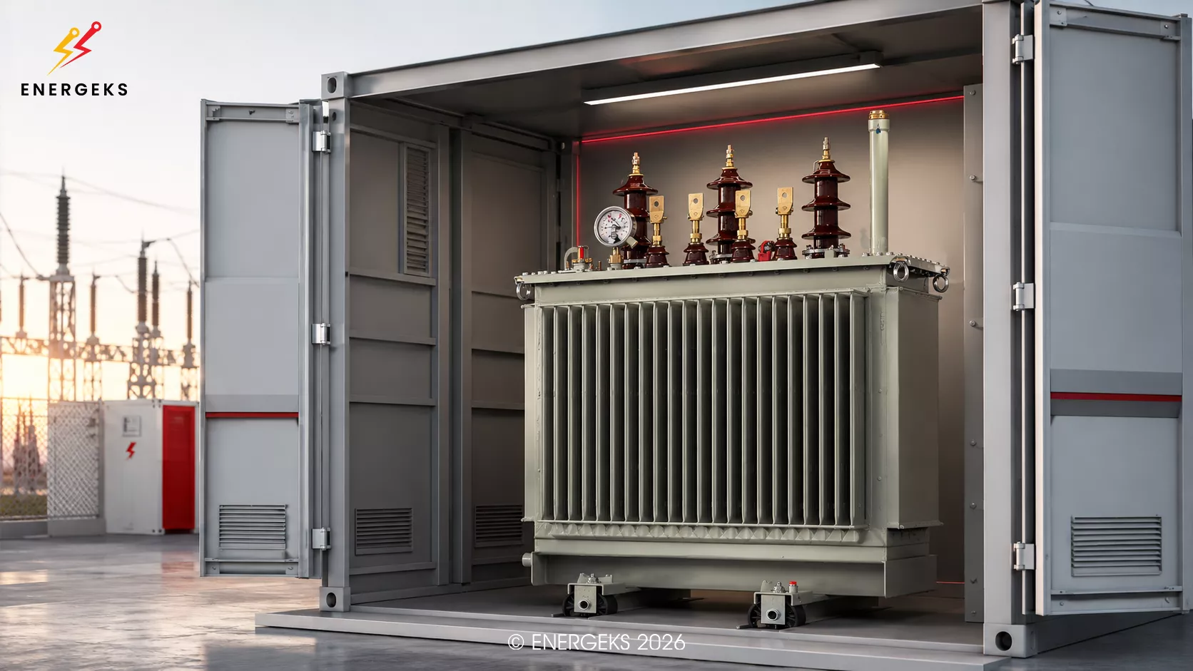
The project is ready.
The documentation is approved.
The foundation is poured. The container is almost ready for transport.
The transformer? Standard. 1250 kVA. What could go wrong?
On the day of delivery, it turns out that the transformer does not fit in the compartment.
Or it fits – on the drawing – but after installing the bushings, cables, covers and radiators, the doors cannot be closed.
Or they can be closed, but there is no way to remove it later without dismantling half the station.
And then the industry sculpture begins.
Modifying the container structure. Moving the switchgear. New busbar connections. Another transport. A call to the investor. A call to the manufacturer. A call to the person who "sent the data sheet, after all".
Costs rise, the schedule starts to resemble a fantasy story, and the transformer – a device that was supposed to simply stand and hum – suddenly becomes the main character of the investment.
And it would have been enough to ask a few proper questions earlier.
Anyone who has ever designed a prefabricated transformer substation (PSS) knows this rule: a transformer is selected not only for the installation's power. It is selected for the entire station – its structure, ventilation, protection, grid conditions and future mode of operation.
At Energeks, we work with MV/LV transformers intended, among other things, for containerised stations, industrial installations, photovoltaic farms and energy storage systems.
We know, therefore, that two transformers of the same kVA rating can have a similar nameplate but completely different dimensions, losses, termination layout, weight, noise level and operational requirements.
This guide should be read by PSS station designers, general contractors, PV and BESS system integrators, electrical engineers and industrial investors.
After reading, you will know:
how to correctly select the transformer power,
when to choose an oil‑immersed transformer and when a dry‑type one,
which dimensions to check before approving the container,
how to calculate the impact of losses on compartment ventilation,
why short‑circuit voltage affects the entire LV switchgear,
what to agree with the transformer manufacturer and the station manufacturer,
and how to avoid mistakes that most often emerge only during assembly.
Reading time: about 10 minutes.
Technically, a transformer standing in a containerised station can be a construction very similar to a standard distribution transformer.
From a design perspective, however, the situation is completely different.
A transformer operating freely outdoors has air around it, space for servicing and relatively good heat dissipation conditions. In a containerised station, it is enclosed in a metal or concrete compartment, often between the MV switchgear and the LV switchgear. Its closest neighbours also produce heat, and in summer, the station enclosure can be additionally heated by the sun.
The transformer does not know that the project looks very elegant in the CAD programme. It reacts to temperature, currents, the magnetic field and the actual amount of air flowing between the radiators.
Prefabricated transformer substations for voltages above 1 kV and up to 52 kV are covered by IEC 62271-202:2022. The standard specifies, among other things, operating conditions, rated parameters, structural requirements and test methods for complete stations. The latest edition also includes an assessment of the influence of solar radiation on the internal temperature of the enclosure and clarifies heating tests.
This is an important distinction:
compliance of the transformer itself with the IEC/EN 60076 series does not automatically mean that the entire station with that transformer will operate correctly.
The transformer and the enclosure must be treated as one thermal, electrical and mechanical system.
Paper will accept anything. The container has a slightly smaller sense of humour.
The most common selection method looks like this:
The load is about 900 kW, so let's take a 1000 kVA transformer.
Sometimes this will be the correct decision.
Sometimes it will be a beautifully packaged problem.
Transformer power is specified in kilovolt‑amperes, i.e., kVA or MVA.
Loads, however, are very often described by active power in kilowatts. To move from one value to the other, the power factor must be taken into account:
S = P / cosφ
For a load of 900 kW and cosφ = 0.9, we get:
S = 900 / 0.9 = 1000 kVA
Theoretically, a 1000 kVA transformer fits perfectly.
The problem is that a perfectly matched transformer is sometimes perfect only in a spreadsheet.
Don't ask only: "how many kilowatts?"
Before selecting the power, you need to determine:
the maximum simultaneous power,
the load profile over the day and year,
the power factor,
the share of motors and their starting currents,
the presence of harmonics,
the possibility of plant expansion,
the ambient temperature,
the direction of energy flow,
expected overloads,
the method of reactive power compensation.
A plant may have a total installed power of 1400 kW but never draw more than 750 kW. It may also have loads of 800 kW that, for a few minutes during startup, behave as if they were trying to start a small steelworks.
That is why what counts is not only the sum of power but also the simultaneity factor and the load character.
Adding a reasonable margin is usually good practice. Buying a transformer twice as large "just in case" – not necessarily.
An oversized transformer:
costs more,
is larger and heavier,
may require a larger station,
generates no‑load losses whenever it is energised,
may increase the available short‑circuit current on the LV side,
may operate for most of the time far from the optimum load point.
No‑load losses occur whenever the transformer is energised, even if the loads are drawing almost nothing. Load losses, on the other hand, increase approximately with the square of the current.
So a transformer bought "with a large margin" may quietly heat the air and the investor's balance sheet for 20 years.
The current ecodesign requirements for transformers placed on the EU market result from Regulation 548/2014, amended by Regulation 2019/1783.
Tier 2 requirements have been in force since July 2021 and limit permissible losses or require a specific efficiency level.
Example: a 1250 kVA transformer
The rated current on the 400 V side is:
I = 1,250,000 / (√3 × 400) ≈ 1804 A
This single result affects:
the cross‑section and number of LV cables,
the busbar construction,
the rated current of the switchgear,
the protection apparatus,
the method of connecting the transformer,
the connection temperature,
the space needed for the terminations.
If the LV side voltage is 800 V, the current drops to about 902 A. The transformer power remains the same, but the connection geometry and switchgear requirements change radically.
Therefore, the information "1250 kVA" without specifying the voltages is about as complete as ordering a car with the description "large, preferably red".
A standard distribution transformer in an industrial plant most often supplies loads.
A transformer on a photovoltaic farm operates mainly with energy flowing from the inverters to the grid. In an energy storage system, the flow direction regularly changes: charging, discharging, reactive power regulation, partial load and fast load cycles.
This is not a cosmetic difference.
For PV and BESS installations, at least the following must be provided to the transformer manufacturer:
the power and number of inverters or PCS units,
the voltage on the inverter side,
the maximum active power,
the reactive power range,
the required cosφ,
the charging and discharging profile,
the expected harmonic content,
the possibility of long‑term operation at full power,
the frequency of load changes,
the MV grid voltage,
the distribution system operator's requirements.
The IEC 60076 series covers not only general transformer parameters but also issues related to harmonics, transport, DC currents, condition monitoring and the functional method of specifying the device.
The conclusion is simple:
a transformer for BESS or a PV farm should not be ordered solely on the basis of inverter power.
An inverter is not a resistive heater. It generates a specific current spectrum, can operate with reactive power and can cause additional losses in the windings and structural components of the transformer.
This is one of the most frequently asked questions.
And as usual in power engineering, the most professional answer is:
it depends.
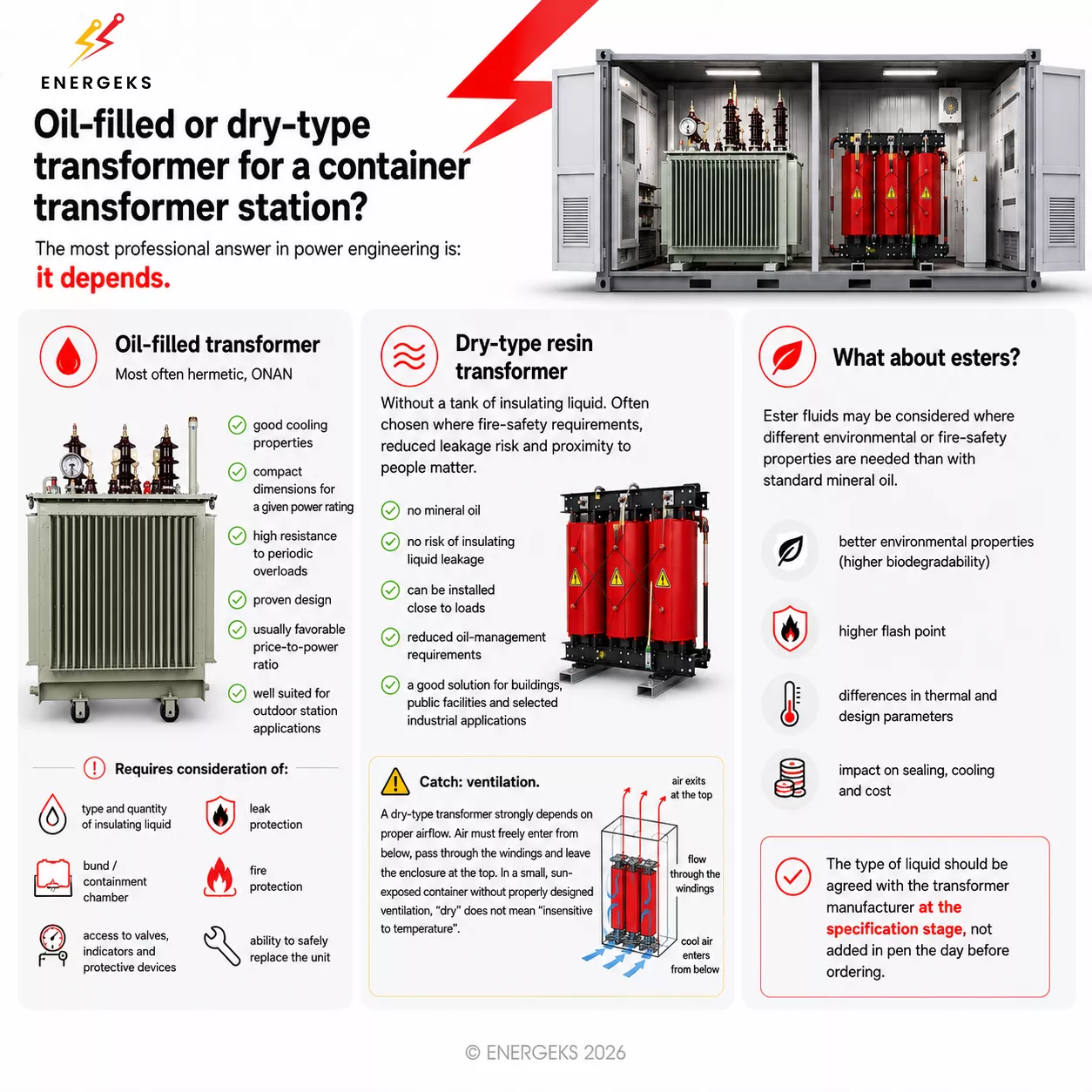
Oil‑immersed transformer
An oil‑immersed transformer, most often hermetically sealed with ONAN cooling, is a common choice for containerised transformer stations.
Its advantages include:
good cooling properties,
compact dimensions for a given power,
high resistance to periodic overloads,
proven construction,
usually favourable price‑to‑power ratio,
good suitability for outdoor station operation.
However, it requires consideration of:
the type and quantity of insulating liquid,
leak protection,
a containment basin or sealed retention compartment,
fire protection,
access to valves, indicators and protections,
the possibility of safe replacement of the unit.
An oil‑immersed transformer can be a very safe solution, but the principle of "let's put it in and the oil will somehow manage" does not apply.
Cast‑resin dry‑type transformer
A dry‑type transformer does not have a tank with insulating liquid. It is often chosen where fire safety requirements, limiting the risk of leakage or location close to people and infrastructure are important.
IEC 60076-11 covers dry‑type transformers, and its scope includes, among other things, environmental, climatic and fire classes, the influence of altitude above sea level, and the operation of the transformer in an enclosure.
Advantages of a dry‑type transformer:
no mineral oil,
no risk of insulating liquid leakage,
possibility of installation close to loads,
limited oil management requirements,
a good solution for buildings, public facilities and selected industrial installations.
But there is a catch the size of a radiator.
A dry‑type transformer is strongly dependent on proper airflow. The air must flow freely from below, pass through the windings and leave the compartment from the top. Manufacturers' installation instructions emphasise the need to ensure ventilation and maintain the air temperature within the transformer's design limits.
In a small, sun‑exposed container, a dry‑type transformer without properly calculated ventilation can quickly remind you that the word "dry" does not mean "insensitive to temperature".
What about esters?
Ester fluids may be considered where different environmental or fire properties than those of standard mineral oil are required.
They should not, however, be treated as a simple one‑to‑one replacement. The type of fluid affects, among other things, the insulation system design, cooling, seals, thermal parameters and the price of the device.
The choice should be agreed with the transformer manufacturer at the specification stage, not added in pen the day before ordering.
The infographic compares an oil‑immersed transformer, a cast‑resin dry‑type transformer and ester‑based solutions for a containerised transformer station, indicating differences in cooling, safety, ventilation, dimensions and operational requirements.
CC: ENERGEKS 2026
One of the most expensive mistakes when designing a prefabricated transformer station is approving its construction based on "typical transformer dimensions".
The problem is that a typical 1000 kVA transformer does not actually exist.
What exists is a specific transformer from a specific manufacturer, with a specific core, losses, radiator arrangement, equipment, cooling method, short‑circuit voltage, bushings and wheel or skid spacing. Two devices with the same power, ratio and connection group can differ in length, width or height by a dozen or so centimetres. Sometimes by several dozen.
On paper, it will still be a 1000 kVA transformer.
In the container, one will fit without any problem, while the other will make the designer start moving walls in the 3D model in the hope that steel will also prove flexible in reality.
Therefore, the length, width and height of the body are only the beginning.
You need to know the maximum outline of the device together with radiators, bushings, terminals and accessories. Also important are the height needed to remove covers, the position of the MV and LV terminals, the wheel spacing, the direction of movement, the total weight, the centre of gravity and the location of the lifting points.
Add to this the space for cable bending radii, insulation clearances and service access.
The transformer may fit in the compartment as a solid block, but after connecting the cables, it may suddenly turn out that the MV cable would have to bend at an angle previously known only from advanced yoga.
Insulation and external air clearance requirements are not an aesthetic suggestion. IEC 60076-3 describes the insulation requirements and recommended clearances between live parts, as well as between live parts and earth. Therefore, missing ten centimetres cannot be recovered by pushing the MV bushing close to a metal wall just because it looks neat in the design programme.
There is one more thing that is easy to forget: the transformer must not only stand in the station. It must first be delivered there.
Therefore, the entire path of the device, from the vehicle to the working position, must be traced. Will it fit through the door? Is the threshold not too high? Will the floor support its weight during rolling? Will there be room for rollers, a winch and manoeuvring? After the other equipment is set up, will the crane still have access to the compartment?
And what will happen in fifteen or twenty years when the transformer needs to be removed?
The station should be designed not only for the day of installation but also for the day of the first major replacement. Sometimes this means a removable wall, sometimes a removable roof, and sometimes a properly planned transport route. What matters is that the solution is created in the design, not during a failure.
A transformer that fits in the compartment with a margin of twenty millimetres does not fit perfectly.
It is simply very politely warning that someone is about to have a problem.
Every watt of transformer losses ultimately turns into heat. It does not disappear in the documentation, it does not dissipate in the schedule, and it cannot be convinced that no space was provided for it in the design.
If the total transformer losses are, for example, 12 kW, inside the station we have a heat source equivalent to several powerful electric heaters working continuously. Add to this the losses of the LV switchgear, busbar connections and cables, and in summer also solar radiation heating the station enclosure.
As a result, the transformer may still have an electrical margin, but thermally it may already be on the edge of reason.
Ambient temperature and load profile affect the operating temperature and insulation ageing. This means that a device operating for years in a compartment that is too hot may formally not be overloaded, but its insulation will age faster than assumed.
Therefore, ventilation cannot be an add‑on written at the end of the project. It must result from the actual transformer losses and the station's operating conditions.
With natural ventilation, the principle is simple: cool air should flow in low, heat up as it passes through the compartment and leave as high as possible. A simple principle, however, does not mean a simple design.
Air, like a person after eight hours on a construction site, chooses the easiest path. If the grilles are poorly placed, it may flow straight from the inlet to the outlet, bypassing the transformer. On the drawing, everything then looks correct; air indeed circulates, but not necessarily where it is needed.
You also need to look at the active area of the openings, not only at their external dimensions. A grille with an area of one square metre does not automatically provide one square metre of free flow. Louvres, insect screens, filters and silencers can reduce the actual cross‑section so effectively that a large opening starts to act like the energy equivalent of breathing through a straw.
Flow resistance, the height difference between inlet and outlet, protection against water, wind and the expected temperature difference all matter. The more restrictive elements there are, the larger the opening may be needed.
If natural ventilation is insufficient, forced ventilation must be used. Then, the choice of fan alone does not end the matter.
The required performance, switch‑on temperature, control method and behaviour of the system after a power failure must be determined. It must also be decided what happens if the fan fails. Will an alarm appear? Will a second fan take over? Is the transformer temperature being sent to the station automation or the supervisory system?
A fan should not be the only thing separating the transformer from overheating if no one knows whether it is still spinning.
Well‑designed ventilation is not spectacular. It does not make noise around itself, it does not require phone calls, and usually no one thinks about it.
In other words, it works exactly as it should.
Short‑circuit voltage is one of those parameters that look innocent until you start calculating short‑circuit currents and selecting the LV switchgear.
For a 1250 kVA transformer with a secondary voltage of 400 V, the rated current is about 1804 A. If the short‑circuit voltage is 6%, the approximate short‑circuit current at the transformer terminals can be estimated using the formula:
Ik ≈ In × 100 / uk
Substituting gives approximately:
Ik ≈ 1804 A × 100 / 6 ≈ 30 kA
This calculation is simplified because it does not take into account the full impedance of the supply grid, cables, busbars and connections. It does, however, show the scale of the problem.
If the short‑circuit voltage is lower, the short‑circuit current will increase. The switchgear, busbars and apparatus will have to withstand greater thermal and dynamic loads. If uk% is higher, the short‑circuit current will decrease, but voltage drops under load will increase, which may, for example, make it more difficult to start large motors.
This one parameter therefore simultaneously affects the selection of the switchgear, circuit breakers, protections, selectivity, voltage drops and the possibility of parallel operation of transformers.
You should not copy the short‑circuit voltage from an old design just because the old design worked.
The fact that the previous installation has not yet caught fire is not a calculation method.
Designations such as Dyn5 or Dyn11 may look like a code written by someone who really did not want to use full sentences. In reality, they convey important information about the winding connection method, the neutral point termination and the phase shift between the MV and LV sides.
The connection group affects the neutral earthing method, the operation of earth‑fault protections, the zero‑sequence current flow and the transformer's compatibility with the existing installation. It is also important when working with inverters, generators and other transformers.
Particular care must be taken with parallel operation. Two transformers with the same power and the same voltages cannot necessarily work together.
They must have compatible connection groups, ratios and phase sequences. The tap positions, short‑circuit voltage values and impedance characteristics are also important. If these parameters differ, circulating currents may appear between the transformers, and the load will not be shared as assumed.
Transformers do not learn to cooperate on an integration trip.
They must understand each other from the nameplate.
The notation 15/0.4 kV looks specific, but it still does not say everything.
You need to know the actual grid voltage conditions, the required insulation level, the highest voltage for equipment Um, the tap range, the number of steps and the value of each step. Also important is at which tap position the nominal ratio is given and what voltage is expected on the LV side during normal load.
In typical distribution transformers, the most common solution is an off‑circuit tap changer. This means that changing the ratio requires the transformer to be de‑energised and disconnected.
It is therefore not a regulator that will automatically correct the voltage in every situation.
If the MV voltage rises during periods of high photovoltaic generation, a poorly chosen ratio can lead to excessively high LV voltage. In a weak grid and under heavy load, the problem can be the opposite – the voltage starts to drop.
Taps allow the ratio to be adjusted to grid conditions, but they will not fix a poorly designed system.
MV and LV terminations: cables also need space
The transformer does not end with the tank and radiators. It must still be connected to the MV and LV switchgear, and the way these connections are made can completely change the compartment layout.
On the MV side, various solutions can be used, including porcelain or plug‑in bushings, with top or side terminations. On the LV side, flat terminals, cables or busbar connections may appear. Each of these solutions requires a different amount of space and different installation access.
Particularly on the LV side, a few centimetres make a huge difference. For a 1250 kVA transformer, the rated current on the 400 V side exceeds 1800 A. For larger units, we are already talking about several thousand amperes.
In such a system, shifting the terminals can force a complete redesign of the busbar bridge.
Therefore, before approving the station structure, you need to know the MV and LV connection side, phase sequence, terminal height and spacing, and the type of terminations. The number of cables per phase, their bending radii, mounting method and the space required for making connections must also be considered.
Busbar connections additionally require consideration of electrodynamic forces, thermal expansion and vibration compensation.
Heavy cables cannot hang on the transformer bushings like a shopping bag on a door handle. They must have their own support and mechanical strain relief to prevent forces from being transferred to the terminals.
It is also worth leaving enough space for a person to use a torque wrench without dismantling half the station and their own wrist.
How to match the clamps to the transformer rating and cable size is covered in how to choose a transformer clamp, and how to install them so they do not overheat in why transformer clamps overheat.
The earthing of the transformer and the entire station must be clearly planned.
You need to determine the earthing method for the LV neutral point, the connection of the transformer tank or structure to the main earthing busbar, the earthing of cable screens, and the execution of equipotential bonding. If the transformer construction requires a separate core earthing termination, it must also be included in the design.
This is not an assembly detail.
The earthing method affects the operation of protections, the values of earth‑fault currents and the behaviour of the entire system under fault conditions. Particular attention must be paid to installations with inverters, EMC filters, non‑linear loads, UPS units and backup sources.
It must also be determined whether the LV neutral point will be brought out and what its current rating should be. In installations with a large number of non‑linear loads, significant third‑harmonic currents and their multiples can appear in the neutral conductor.
In such a situation, the neutral is not an add‑on to the three phases.
Noise and vibrations: the transformer is not loud until it stands next to a bedroom
Every transformer makes a sound. It arises primarily from phenomena occurring in the core and electromagnetic forces acting on the windings.
In an open space, it may be barely noticeable. Once the device is enclosed in a container, the situation can, however, change.
The station enclosure may attenuate some of the sound, but it may also reflect waves, amplify certain frequencies and act like a resonance box. Vibrations can pass through the floor to the foundation and then to adjacent structural elements.
Therefore, for locations near houses, offices, hospitals or other noise‑sensitive facilities, it is not enough to state that the transformer "is quiet".
You need to know the guaranteed sound power level, assess the foundation design, the method of supporting the device, and the influence of fans and louvres. It is also worth analysing the connections between the transformer and the switchgear.
Anti‑vibration pads will do little good if the transformer is connected to the station structure by a rigid busbar bridge that will transmit vibrations further like a professional courier.
Noise should therefore be analysed as a characteristic of the entire station, not only of the transformer. The device itself may meet the requirements, but the container, foundation and ventilation will decide what a person standing on the other side of the fence ultimately hears.
Also read:
How not to burn a million? Principles of building a transformer station for heavy industry
A good request for quotation does not need to have 40 pages, five attachments and an eagle stamp.
It should, however, contain enough information that the transformer manufacturer does not have to guess whether the device is to supply a production hall, a PV farm, an energy storage system or perhaps a small power plant hidden under the name "office building".
The more key data you provide at the beginning, the fewer phone calls, clarifications and magic phrases like "it depends" there will be.
And most importantly – the greater the chance that the offer you receive will be for a transformer you actually need, not for one that happened to be easiest to quote.
⚡ First, the electrical side, because the transformer does live on voltage
To start with, you need to state how much power you need. The value in kVA or MVA is the foundation of the entire enquiry. Without it, the conversation resembles a visit to a restaurant and asking: "how much does the food cost?"
Power alone is not enough, however. The MV and LV voltages, frequency and expected connection group are needed. These parameters determine which grid the transformer will work with and whether, after connection, everything will play according to the design or whether experimental installation jazz will be created.
The short‑circuit voltage should also be provided. This small percentage has a very large impact on short‑circuit currents, protection selection, voltage drops and cooperation with the switchgear. uk% should not be copied from the last project just because "it was also 6% there and it worked".
Another issue is the tap range and the number of available steps. The grid does not always behave exactly as on the single‑line diagram, so it is good to know whether the transformer should allow ratio correction and in what range.
Add to this the insulation level, required no‑load and load loss values, and noise expectations. The last parameter often appears only when the transformer starts working five metres from an office, a house or a gatehouse, and someone discovers that the "gentle hum" has its own acoustic life.
⚡ Next, tell us what this transformer will actually be doing
Two transformers with the same power can have completely different working lives.
One quietly supplies lighting, ventilation and a few production lines for most of the year. Another handles heavy motors, inverters, welders or the PCS of an energy storage system that constantly changes the direction of power flow. They may look similar on the nameplate, but their daily life is completely different.
Therefore, the type of load and the maximum active power must be described. It is worth providing the power factor cosφ or the reactive power range, especially when inverters, compensation or power electronics are present in the installation.
The operating profile is very important. A transformer handles continuous 24‑hour load differently, short peaks differently, and regular overloads differently again. It is therefore good to indicate whether it operates for 24 hours, only on one shift, seasonally, or perhaps in summer it gets more work precisely when the temperature in the container starts to resemble the inside of an oven.
If motors are present in the system, the starting currents should be given. If there are inverters, rectifiers, UPS units or chargers, harmonics should be mentioned. You do not need to immediately send a doctoral thesis on power quality, but information about the load character can prevent the selection of a transformer for conditions it will never actually see.
It is also worth specifying the direction of energy flow. In a classic plant, energy flows from the grid to the loads. In PV and BESS installations, the situation can reverse, sometimes several times a day. If parallel operation with a second transformer, generator or other source is planned, this should also be stated straight away. The transformer does not like integration surprises.
⚡ The container stands in the real world, not in a neutral CAD environment
Environmental conditions are often treated as an add‑on to the specification. This is a mistake, because the transformer does not work in a catalogue; it works in a specific location.
It must be stated whether the device will be installed indoors or outdoors. In the case of a containerised station, "outdoors" does not yet mean that the transformer has comfortable access to fresh air. It can still be enclosed in a metal compartment that collects sun like a solar frying pan for several hours a day.
The minimum and maximum ambient temperatures, altitude above sea level, humidity and dust level should be provided. Altitude matters for cooling and insulation, humidity for the risk of condensation, and dust for ventilation and cleanliness of insulating surfaces.
If corrosive substances, salt atmosphere, chemicals or aggressive industrial dusts are present in the surroundings, the manufacturer must know about it. A station at a chemical plant, wastewater treatment plant, cement works and a quiet logistics centre do not operate in the same conditions, even if all the projects have equally aesthetic covers.
It is worth specifying the requirements regarding condensation and the station's exposure to solar radiation. A container placed in the shade between buildings and a container standing alone on an open plot in full sun are two different microclimates. The transformer will notice the difference faster than the user.
⚡ Then comes the mechanics – the moment when centimetres regain power
A transformer can have ideal electrical parameters and still be unsuitable for a specific station because it is too wide, too tall, too heavy or has terminations on the wrong side.
Therefore, the maximum permissible dimensions and weight of the device should be provided in the enquiry. And it is not only about the dimensions of the tank or windings themselves. The radiators, bushings, accessories, boxes, valves, brackets and everything that in the real world protrudes beyond the elegant rectangle from the drawing must be taken into account.
The direction of the MV and LV terminations should also be clearly specified. This helps to avoid a situation where the switchgear is waiting on the left, the transformer has terminals on the right, and someone is trying to create a connection arrangement between them that resembles an art installation.
The type of connections must be matched to the method of connection to the switchgear. Different solutions are used for cables, different for busbar bridges, and different again for plug‑in bushings. It is worth providing the requirements regarding phase sequence, terminal spacing and connection height.
If the transformer has wheels or skids, their spacing and direction of movement should be specified. This is important for the guides, the station floor and the method of introducing the device into the compartment.
Transport also needs to be described. Will the transformer be slid through the door, lowered through the roof, introduced on rollers, or will the entire station be assembled around it? The door dimensions, floor load‑bearing capacity, crane access and manoeuvring space are not logistical details. They are part of the design.
At this stage, it is also worth specifying the additional equipment: temperature indicators, sensors, protections, alarm contacts, monitoring, valves, relays, fans, enclosures, bushings or other elements required by the investor and the station automation.
⚡ Finally, documentation – everything that everyone suddenly needs "for yesterday"
A good enquiry should specify what documentation you expect and when it is to be delivered.
The basis is the dimension drawing. It allows the station manufacturer to check whether the transformer really fits in the compartment, whether it has adequate space for connections and whether it can be safely installed.
A data sheet and a loss summary will also be needed. Losses are important not only for assessing efficiency but also for ventilation calculations and the thermal balance of the compartment.
Depending on the project stage and the investor's requirements, test reports, a nameplate template, transport, installation and commissioning instructions, and the relevant declarations of conformity may also be required.
It is also worth asking for a full equipment list. Nothing improves the atmosphere on site like discovering that an element considered by one side to be an "obvious standard" was treated by the other as a paid option that no one ordered.
It is also very good to establish a documentation approval schedule. First the data sheet and drawing for approval, then production, then the final documentation. This order seems logical, but in the industry, there are still projects where the drawing for approval reaches the client when the transformer is already slowly drying after painting.
⚡ One good enquiry saves ten nervous phone calls
You do not need to know all the parameters from day one. If some data is still being agreed, simply note it in the enquiry. What matters is that the manufacturer knows which values are approved, which are indicative and which may still change.
The worst enquiry reads:
"Please quote a standard 1000 kVA transformer for a container."
The best does not have to be long, but should clearly describe the device, operating conditions, mechanical limitations and the expected scope of documentation.
Because the transformer manufacturer can advise, optimise and propose the right solution. They should not, however, be forced to telepathically reconstruct the project based on one number and an attachment named "final_v7_ultimate_corrected.pdf".
Do not start with the question: how much does the transformer cost?
First, check where it will operate, what it will supply, how it will be loaded, and whether it will actually fit in the station – together with connections, ventilation and service space.
A good transformer must fit the project electrically, mechanically and thermally. Ideally, so that after commissioning, no one has to save the investment with phone calls, modifications and industry survival.
We thank the designers, contractors, integrators and investors who invite us to talk early enough. That is when we can jointly select a solution that will operate calmly and reliably for years.
⚡ At Energeks, we help select oil‑immersed and dry‑type transformers for prefabricated transformer stations, industrial plants, photovoltaic installations and energy storage systems. We analyse not only the rated power but also the grid conditions, connection system, short‑circuit voltage, losses, dimensions, cooling and the actual operating profile.
We do not look for the largest transformer or the cheapest solution at all costs. We look for a configuration that, after commissioning, will simply do its job – calmly, efficiently and without nervous phone calls.
Explore the Energeks transformer range
Are you working on a project where delivery time is critical?
Check the transformers available off‑the‑shelf from our warehouse
And if you want to follow our projects, technical guides and industry stories without corporate frosting – join Energeks on LinkedIn.
Let's talk about your project as partners. Before the transformer goes into the container, not when it turns out that the container has its own opinion on the matter.
references:
International Electrotechnical Commission, IEC 62271-202:2022 — AC prefabricated substations for rated voltages above 1 kV and up to 52 kV.
International Electrotechnical Commission, IEC 60076 series — Power transformers.
European Commission, Power Transformers — Ecodesign requirements and Tier 2 efficiency provisions.
Shipped from our warehouse in Poland within 2–3 working days, 5-year warranty. Full range 25–2500 kVA in the shop (prices in PLN).
No reviews!