10 Sep
2026
Energeks

The connection between a cable and the LV bushing stud carries hundreds of amps. A small rise in contact resistance is enough to release tens of watts of heat at a single point – and that heat goes straight into the stud, the bushing insulator and its seal. Below: where hot clamps come from, how to avoid them during installation and how to catch them before they cause a failure.
The power lost in a joint is P = I² × R. On a 630 kVA transformer the LV phase current is about 900 A. At that current every extra 0.1 mΩ of contact resistance means about 81 W of continuous heating in a single clamp. A hot contact oxidises faster, its resistance keeps rising and the process feeds itself.
Clamping screws tightened “by feel” or never checked after commissioning. Conductors – aluminium ones in particular – settle under pressure and the clamping force drops over time.
Crushed strands, stripped threads, a cracked body. Tighten the screws with a torque wrench, gradually and alternately – not with brute force and not with an extension on the wrench.
Oxide on an aluminium conductor, a dirty stud, paint residue. Clean the conducting surfaces immediately before installation. TOC clamps accept aluminium and copper conductors – the tin-plated body limits corrosion at the contact with aluminium, but the conductor still has to be cleaned.
Stripped too short (insulation under the screw) or too long (bare conductor sticking out of the socket), a cross-section outside the socket range, or a conductor shape the clamp is not designed for.
Heavy LV cables that are not supported bend and twist the stud. This increases the risk of a loose joint, bushing damage and oil leaking past the seal.
After an installation is extended, the current is often higher than the one the connections were chosen for – and it is not only the clamp that heats up. More on running a transformer near its limit in our article on transformer ageing.
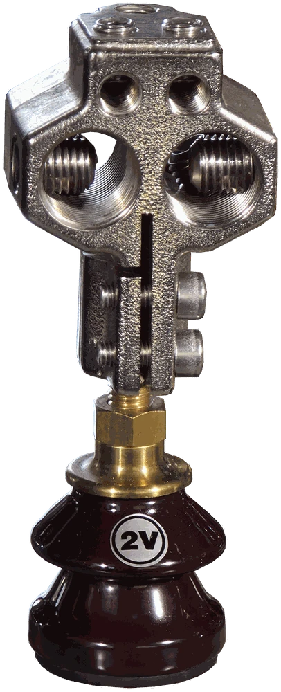
A set of TOC-1 clamps on the LV bushings – sockets aligned with the cable route.
Thermography finds a bad contact without switching the transformer off. For the result to mean something:
A useful reference are the criteria of the US standard ANSI/NETA (table 100.18), used by many inspection companies:
| ΔT between similar components | ΔT above ambient | Recommended action |
|---|---|---|
| 1–3 °C | 1–10 °C | possible deficiency – investigate |
| 4–15 °C | 11–20 °C | probable deficiency – repair as time permits |
| – | 21–40 °C | monitor until corrective action is taken |
| > 15 °C | > 40 °C | major discrepancy – repair immediately |
If the grid operator or the plant has its own operating instructions with different thresholds, those apply.
Regular inspection costs a fraction of a repair – see what a professional transformer overhaul looks like. If a clamp needs replacing, start with choosing the transformer clamp for the rating – ready-made sets are in our transformer clamps category.
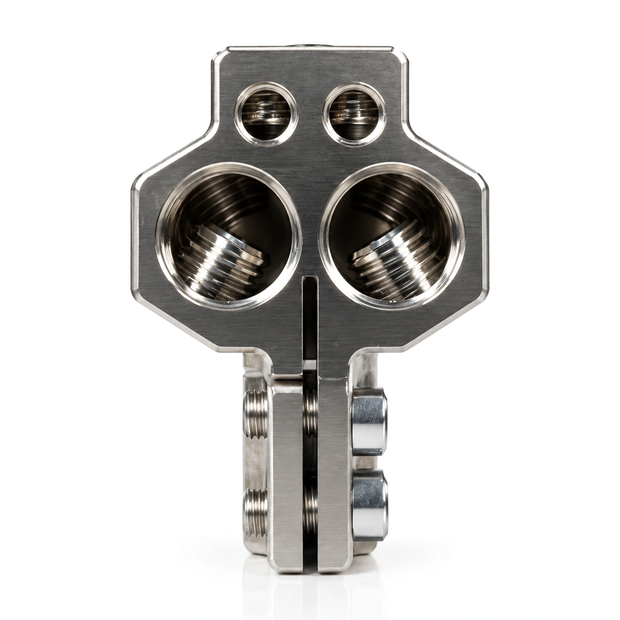 TOC-1 – horizontalM12 / M20 / M30, 250–1000 A, 2 × 300 mm²
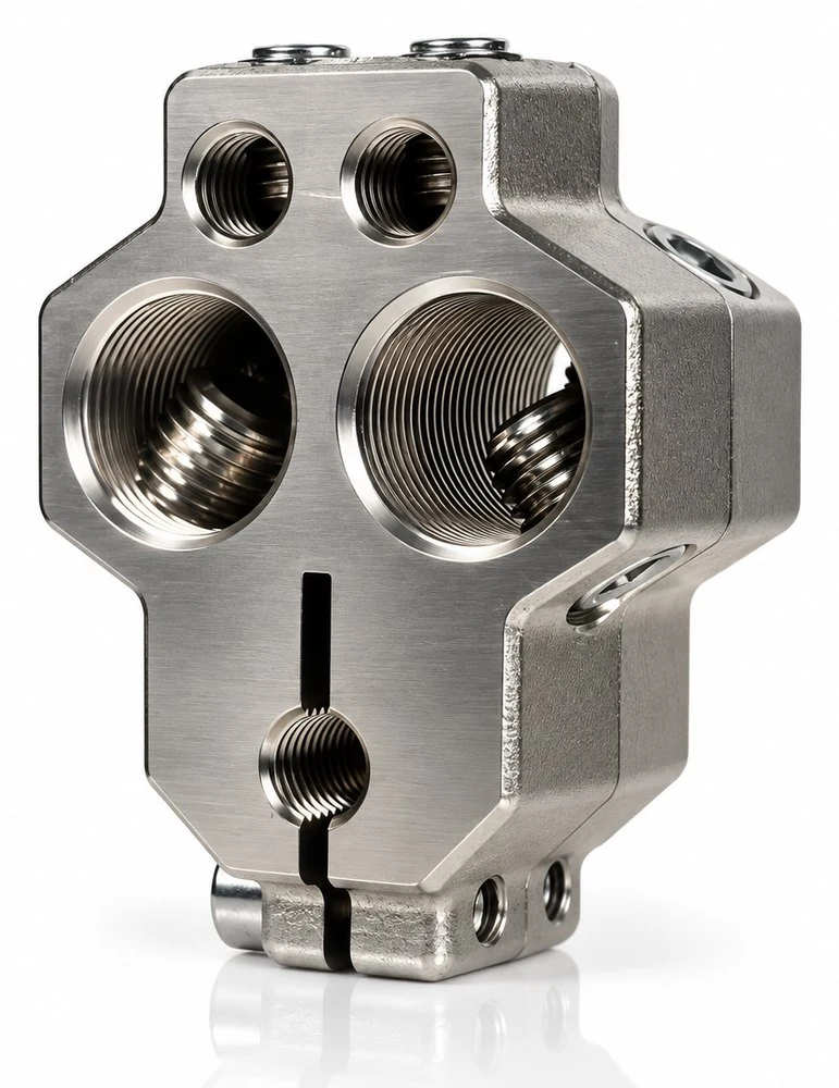 TOC-2 – compactsame connection capacity, smaller footprint
No reviews!