6 Jul
2026
Energeks

Transformers, transformer stations, MV/LV switchgear and infrastructure for renewables are all part of the same puzzle. An energy storage system is not a lonely island. It is an element of a system that must communicate with the grid, the inverter, protection devices, automation, and the operator's requirements.
This article is for renewable energy investors, designers, general contractors, industrial plants, PV+BESS farm developers, and everyone who wants to understand why a transformer for an energy storage system should not be selected like a standard transformer from a catalogue.
We often imagine an energy storage system as one large battery: containers, lithium‑ion modules, a cooling system, inverters, monitoring, algorithms. But in practice, all this technology is of little use if the energy cannot safely enter the grid and return from it.
And this is where the transformer enters the stage.
It is the gateway between the world of batteries, inverters and the PCS system, and the medium‑voltage grid. A bit like a lock in a canal: on one side we have the dynamic, fast, electronic world of the energy storage system; on the other – the stable, demanding and unforgiving power grid.
If the lock is poorly chosen, the whole project begins to lose efficiency, reliability and predictability.
The energy storage market is growing very rapidly.
According to the IEA, energy storage was the fastest‑growing commercially available energy technology in the power sector in 2023, with global battery storage additions reaching 42 GW.
This means one thing: more and more investors will have to ask themselves not only "which energy storage system to choose?" but also: "which transformer to select so that this storage system really works well?"
In the text, we will cover:
the role of the transformer in a BESS system,
the differences between a transformer for PV, industry and energy storage,
power rating selection in kVA/MVA,
the choice between oil‑immersed and dry‑type transformers,
the impact of harmonics, cyclicity and bidirectional operation,
the mistakes that most often cost the most,
a practical checklist for RFQ specifications.
Reading time: about 10 minutes
The biggest mistake at the start?
Treating energy storage as a larger version of a backup installation.
Yes, a storage system can serve an emergency function. It can supply a facility when the grid is not working.
It can stabilise voltage, reduce peak power demand, or cooperate with photovoltaics. But a modern BESS, or Battery Energy Storage System, is not just a battery.
It is a power system with its own dynamics.
IEC TS 62786-3:2023 describes the requirements for stationary battery energy storage systems connected to distribution networks, including connection schemes, switchgear, operating range, active and reactive power response, power quality, protection, monitoring, control and grid‑connection tests.
The very list of these areas shows that an energy storage system is an active participant in grid operation, not just a consumer or a simple source.
A transformer in such a system must therefore do more than the classic "step up the voltage".
It must work with inverters, withstand variable load profiles, respond to bidirectional operation, and function in an environment where power electronics generate different phenomena than a traditional industrial consumer.
What exactly does a transformer do in an energy storage system?
In simple terms: the transformer matches the voltage of the PCS/inverter system to the grid voltage or the facility's internal installation.
On the battery side, we have direct current. The PCS system converts it to alternating current.
Then the transformer steps up the voltage to the level required by the LV or MV grid, most often in industrial and renewable projects to medium voltage.
But that is only the simplest description.
In reality, a transformer in a BESS system performs several functions simultaneously:
it galvanically isolates the storage system from the grid,
it matches voltage levels,
it affects the earthing method and protection operation,
it limits the transfer of some disturbances,
it must withstand loads resulting from inverter operation,
it operates both during charging and discharging of the storage system.
In a classic PV farm, the energy flow is essentially unidirectional: from the panels through the inverters to the grid. In an energy storage system, energy flows in both directions.
In the morning, the storage system may charge from the grid or from PV; in the afternoon, it may discharge; in the evening, it may operate in price arbitrage; and at night, it may provide a system service.
The transformer therefore does not have one "calm" operating profile.
It has a daily rhythm resembling breathing: inhale, exhale, pause, fast response, repeat.
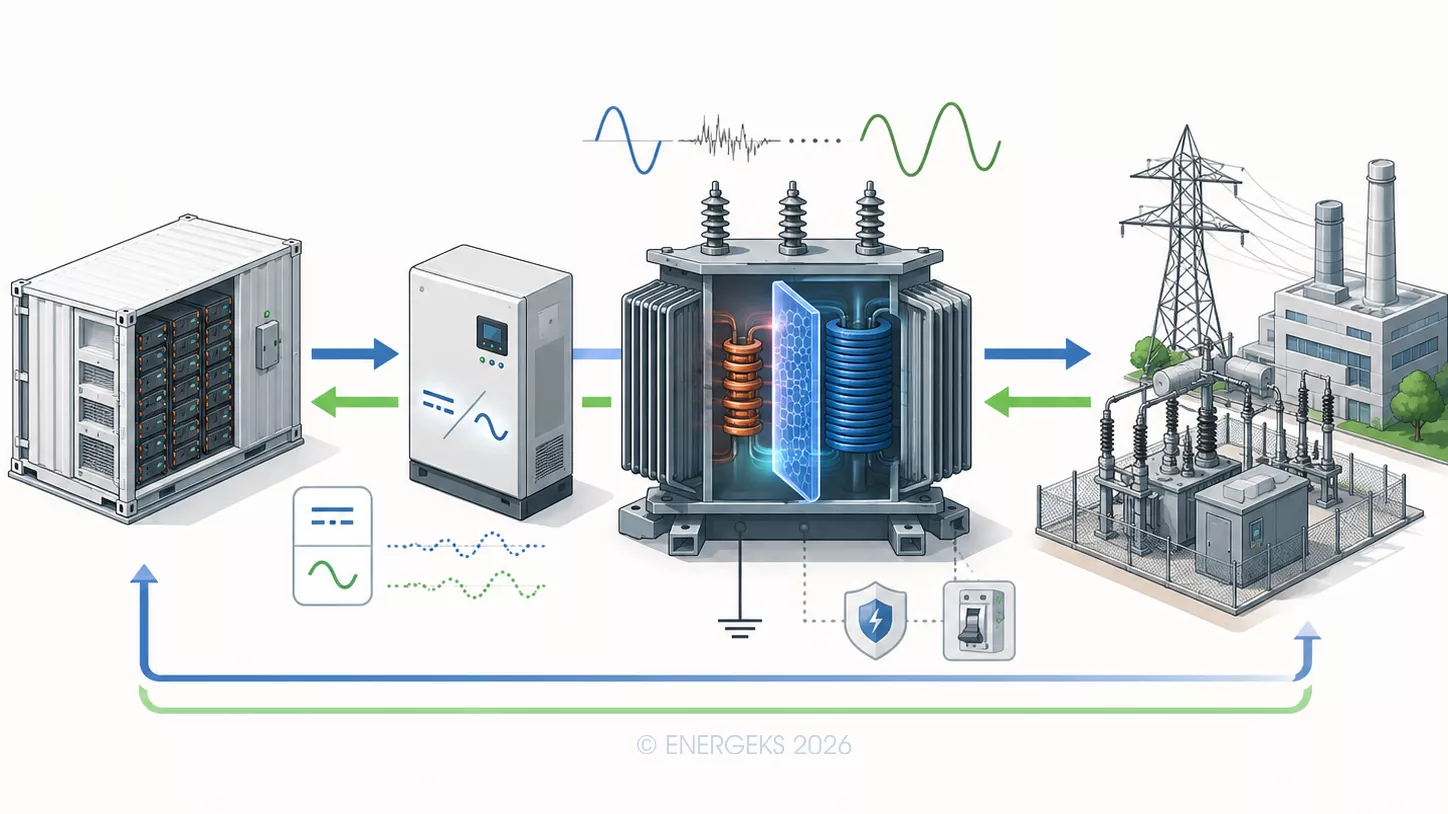
The infographic shows a simplified diagram of a transformer's operation in an energy storage system. On the left is a battery container, from which energy goes to a PCS inverter that converts DC to AC. The central element is the transformer, which matches voltage levels, isolates the storage system from the grid, supports earthing and protection, and limits some disturbances from the power electronics. On the right, the power grid and industrial infrastructure are shown. Bidirectional arrows symbolise charging and discharging of the storage system, i.e., the flow of energy both from the battery to the grid and from the grid to the battery.
CC: ENERGEKS 2026
We do not select a transformer "just because".
We select it for a function.
A different transformer will make sense for an industrial plant that wants to reduce its contracted capacity. Another for a PV farm with a 10 MW/20 MWh storage system.
Another for a large grid‑scale storage system that is to provide balancing and regulation services or support a local grid node.
Before selecting a transformer, several questions must be answered:
Will the storage system operate mainly behind the meter, i.e., on the consumer's side?
Will it be connected as an independent unit to the grid?
Is it to cooperate with a photovoltaic farm?
Will it charge from the grid, from PV, or from both sources?
Will it frequently switch from charging to discharging?
Is it to supply reactive power?
Does the operator require a specific voltage regulation range, communication and observability?
These are not formal questions. They are questions that determine winding temperature, losses, power margin, connection group, cooling type and insulation durability.
This is the point where it is easy to fall into a trap.
An energy storage system is usually described by two parameters: power and capacity.
Example: 5 MW / 10 MWh. The first value tells you how much power the system can charge or discharge. The second tells you how long it can maintain that power.
We do not select a transformer directly based on MWh.
The transformer "sees" primarily apparent power, i.e., kVA or MVA, and the load profile over time.
If the storage system has a PCS power of 5 MW and is to operate at a power factor of 1, the minimum apparent power is theoretically about 5 MVA.
But if reactive power supply or absorption is required, operation at cosφ = 0.9, or a wider regulation range, the apparent power increases.
For example:
5 MW / 0.9 = 5.56 MVA
This means that a 5 MVA transformer may be too tight if the system is to operate dynamically and provide additional grid services. In practice, the designer may consider a 6.3 MVA unit, but the final choice depends on the PCS requirements, the operator, the operating profile, environmental conditions and the overall system architecture.
Similarly for a 2 MW storage system:
2 MW / 0.9 = 2.22 MVA
Here, a natural point of analysis may be a 2.5 MVA transformer, but not as an "automatic answer", only as a result of calculations and coordination with the rest of the system.
⚡ The most important rule: MWh capacity tells you how large the "energy tank" is.
MW power and operating requirements tell you how wide the "pipe" through which this energy flows must be. We select the transformer for the pipe, not for the tank itself.
This is one of the most common questions from investors.
The answer is: it depends on the location, power, fire risk, environmental conditions and the facility's requirements.
Oil‑immersed transformer for energy storage
An oil‑immersed transformer is very often a natural choice for larger energy storage systems, PV+BESS farms and outdoor transformer stations.
It has high heat dissipation capability, good overload capacity, a wide range of available powers, and performs well in outdoor applications.
In containerised projects and MV stations, an oil‑immersed transformer can operate as part of a compact infrastructure: energy storage, PCS, switchgear, transformer, metering and protection system. For larger powers, oil gives the designer greater thermal flexibility.
It is worth remembering, however, the requirements for oil containment basins, environmental protection, clearances, fire protection and site approvals.
In special environmental conditions, the use of esters can be considered, but this too should result from the design, not from fashion.
Dry‑type transformer for energy storage
A dry‑type transformer, especially cast‑resin, is a good solution where fire safety, indoor operation, limiting the risk of insulating liquid leakage, or location near utility infrastructure are important.
In energy storage systems installed at industrial plants, logistics centres, commercial facilities or technical buildings, a dry‑type transformer may be more acceptable from the point of view of health and safety, the insurer and the building designer.
However, it is more sensitive to cooling conditions.
It does not like being "closed in a cupboard" without airflow and expected to work like a transformer in an ideal test hall.
Ventilation, ambient temperature, dust, humidity and service space are of great importance here.
In a typical industrial consumer, energy flows from the grid to the plant. In a classic PV farm, it flows from the source to the grid. In an energy storage system, it flows in both directions.
During charging, the transformer works as an element supplying the storage system. During discharging, it becomes part of the energy export path. This affects:
protection selection,
directionality of measurements,
automation,
MV/LV protection settings,
operator requirements,
active and reactive power flow analysis.
For this reason, the transformer for an energy storage system should be designed together with the PCS system, switchgear, protection and connection scheme. It should not be added at the end like a missing piece.
CIGRE, in its guidelines for BESS connection stations, indicates that the design of such infrastructure covers the entire life cycle: from design and development, through commissioning, to asset management, including output power assessment and parameters at the PCC. This is important because the transformer is not a separate product in a vacuum. It is part of the entire storage system's capability to operate at the point of connection.
Inverters and power electronic converters are the heart of an energy storage system. Without them, the battery could not cooperate with the AC grid. But power electronics generate phenomena that cannot be ignored.
One of them is harmonics.
Harmonics can increase additional losses in the windings and structural components of the transformer. They can cause additional heating, affect insulation durability and require appropriate thermal margin. It is a bit like driving a car on a smooth motorway and on cobblestones. The average speed may look similar, but the suspension load is completely different.
Therefore, when selecting a transformer for BESS, it is worth requiring data on:
the harmonic spectrum generated by the PCS,
current and voltage THD,
switching frequency,
filtering requirements,
permissible power quality levels,
operation under partial load.
IEC TS 62786-3:2023 covers, among other things, power quality, EMC, interface protection, active and reactive power response, and grid‑connection tests. This shows that the transformer for an energy storage system must be selected in the context of the entire electrical environment, not only voltage and rated power.
In energy storage systems, much attention is paid to battery, inverter and cooling system efficiency. The transformer is often treated as an obvious element. That is a mistake.
A transformer has no‑load and load losses. No‑load losses occur when the transformer is energised, even if the storage system is not operating at full power. Load losses increase with current flow.
A simple example like a power bill:
If a transformer has 3 kW of no‑load losses and is energised all year round, that gives:
3 kW × 8760 h = 26,280 kWh per year
That is over 26 MWh of energy lost annually on no‑load alone. For larger units, several transformers or a long project life, the difference between an average and an optimised solution can mean tens or hundreds of megawatt‑hours of losses over the entire operating life.
In an energy storage system that earns money from price differences, flexibility services or peak demand reduction, every unnecessary loss is like a leak in a tank. Small, seemingly. But it works every day.
The selection of a transformer for BESS starts with voltages.
On one side we have the PCS voltage, often at LV level. On the other side we have the MV grid, e.g., 15 kV, 20 kV or another level specified in the connection conditions. The transformer must match these worlds not only in voltage but also functionally.
Important parameters are:
primary and secondary voltage,
rated power,
connection group,
short‑circuit voltage,
tap‑changing range,
insulation level,
neutral earthing method,
parallel operation requirements,
compatibility with protections.
The connection group is not cosmetic. It affects phase shift, behaviour during earth faults, zero‑sequence current flow and protection coordination. In projects with multiple PCS units, an architecture with several block transformers instead of one large unit can be considered. This can improve modularity, serviceability and availability.
In Poland, an energy storage system does not end with the container and the detailed design. It ends when it can be safely connected, commissioned and operated in accordance with the operator's requirements.
TAURON Dystrybucja indicates that, in agreement with the DSOs associated in PTPiREE, procedures for obtaining a permit for use for type D electricity storage systems were developed, effective from 31 March 2026. The same page gives the maximum power thresholds for types B, C and D: 0.2 MW, 10 MW and 75 MW respectively.
This is important because, as the project power increases, not only the transformer power increases. The number of requirements regarding documentation, observability, controllability, tests, protections and connection conditions also increases.
URE also informed about new "General Application Requirements" resulting from NC RfG, which came into force on 1 December 2025 for type B, C and D units for which connection conditions are issued from that date. In practice, this means that BESS projects, especially hybrid PV+BESS or those connected as active grid resources, should be analysed not only from the equipment side but also from the formal‑technical requirements side.
A photovoltaic farm and an energy storage system look like a natural pair. PV produces energy when the sun shines. The storage system allows its use to be shifted in time, reduces curtailment, smooths the generation profile or increases self‑consumption.
But for a transformer, such a system can be more demanding than the PV farm alone.
Why?
Because PV generates energy in a specific daily profile, dependent on insolation. BESS can charge and discharge according to market, grid or industrial strategy. Sometimes the energy from PV feeds the grid, sometimes it charges the battery, sometimes the battery discharges to the grid, and sometimes the whole system operates with export power limitation.
The transformer must be selected for the real power flow scenario, not just the sum of nameplate powers.
Example:
A 20 MWp PV farm and a 10 MW / 20 MWh storage system do not automatically mean that the transformer must be 30 MVA. If the connection conditions limit export to 20 MW and the EMS strategy monitors the operating profile, the selection may look different. However, if the system is to have the ability for fully independent operation of the source and the storage system, the transformation power requirement may be greater.
This is the moment when simulations, connection conditions and a clear EMS strategy are needed. Without this, transformer selection is like choosing a bridge without knowing how many trucks will cross it and in which direction.
In industry, energy storage often has a very practical function: to reduce peak demand, improve PV self‑consumption, provide reserve, stabilise the operation of loads or reduce contracted capacity costs.
Here, the transformer may be part of an existing plant station or new infrastructure dedicated to the storage system. The choice between a dry‑type and oil‑immersed transformer depends on the location.
If the storage system is located next to a production hall, in a technical building or close to people, a dry‑type transformer may be the natural choice. If the system is larger, installed outdoors and operates in a containerised station, an oil‑immersed transformer may be more advantageous in terms of thermal performance, power and cost per MVA.
For industry, the following are particularly important:
noise,
installation location,
fire safety,
service access,
compatibility with existing switchgear,
operation with sensitive loads,
expandability.
An energy storage system in a plant should not be designed as a gadget for invoice optimisation.
It is a new active element of the internal power network.
In large grid‑scale projects, the transformer becomes part of a block architecture.
Instead of one huge unit, several blocks are often used: PCS + block transformer + MV switchgear, followed by a power take‑off to the main station.
Such architecture gives greater flexibility, facilitates servicing and limits the consequences of failure of a single component.
For a 50 MW / 100 MWh storage system, several blocks of 5 MW, 10 MW or more can be considered, depending on the PCS used and the connection concept. Then the question is not only "which transformer?" but "which transformation architecture gives the best compromise between efficiency, availability, cost and risk?".
This is especially important when the storage system is to earn money from system services. Failure of one transformer in a modular system can limit the power of part of the system. Failure of one central element can stop a much larger part of the project.
Selecting a transformer for an energy storage system does not start with the question: "how much does a 2.5 MVA transformer cost?"
It starts with a much more interesting question: how will this storage system really operate?
Because BESS is not a fridge that simply draws power from a socket. It is an active power system that sometimes draws energy, sometimes gives it back, sometimes supports the grid, sometimes charges from PV, and sometimes does everything so dynamically that the classic approach of "let's choose a transformer with some margin and it will be fine" starts to resemble driving a sports car on wheelbarrow tyres.
We advise on the selection of transformers for energy storage systems based on actual operating parameters, not just a single power value from a table.
Below, we show what data is worth preparing and why each item matters.
PCS power in MW – how wide the energy flows
PCS power determines how much power the storage system can charge and discharge. This is one of the most important parameters for transformer selection, because the transformer must handle the actual power flow between the inverter and the grid.
If the PCS has a power of 2 MW, 5 MW or 10 MW, the transformer must be selected not only for that value but also for the system's operating mode. Will the storage system operate continuously? Will it respond to demand peaks? Will it provide grid services? Will it frequently change the direction of energy flow?
PCS power is not just a number. It is the rate at which energy "breathes" through the transformer.
Storage capacity in MWh – how large the energy tank is
Storage capacity, expressed in MWh, tells us how much energy the system can store. We do not select the transformer directly based on MWh, but this value helps to understand how long the storage system can operate at a given power.
A 5 MW / 10 MWh storage system can operate at full power for about 2 hours. A 5 MW / 20 MWh storage system can do so for about 4 hours. For the transformer, this means a completely different thermal profile.
A short power pulse is one thing. Several hours of regular operation under high load is another conversation. The transformer does not get offended immediately, but the winding temperature remembers everything.
Maximum charging and discharging power – because BESS works in both directions
In a classic consumer, energy flows from the grid to the consumer. In a PV farm, most often from the source to the grid. In an energy storage system, we have bidirectional movement.
Therefore, we need to know the maximum charging power and the maximum discharging power. Sometimes they are the same, sometimes different. This affects the selection of transformer power, protection, measurement and the whole system logic.
A transformer in BESS does not have the quiet life of a retiree. It is more like a goalkeeper at an airport: sometimes it lets energy through in one direction, sometimes in the other, and all the time it has to keep order.
Required cosφ or reactive power range – not only active power keeps the grid alive
Active power, expressed in MW, does useful work. But the power system also needs control of reactive power. That is why we ask about the required power factor cosφ or the range of operation with reactive power.
Why is this important?
Because the transformer is selected for apparent power, i.e., kVA or MVA. If the storage system is to operate at cosφ = 1, the situation is simpler. If it is to operate at cosφ = 0.9 or supply/absorb reactive power according to the operator's requirements, the required apparent power increases.
Example:
5 MW at cosφ = 1 means about 5 MVA.5 MW at cosφ = 0.9 already means about 5.56 MVA.
The difference is not academic. It can decide whether the transformer will operate with a comfortable margin or whether it will ask the designer every day: "did you really think that about me?"
PCS side voltage – the starting point for transformation
The PCS, or Power Conversion System, operates on a specific voltage side. The transformer must be matched to the inverter's output voltage and safely step it up to the grid or facility installation level.
This is a basic parameter, but it should not be treated routinely. A different PCS voltage means a different winding configuration, different currents, different losses and different protection requirements.
Simply put: before the transformer steps up the voltage, it must know which step it is starting from.
Grid voltage on the MV/LV side – where the energy is to go
On the other side of the system, we have the low‑voltage or medium‑voltage grid. In industrial and renewable projects, we most often talk about connection to medium voltage, e.g., 15 kV, 20 kV or another level specified in the connection conditions.
This parameter determines the transformer ratio, insulation level, MV switchgear, surge protection and compliance with the operator's requirements.
The transformer is the interpreter between the language of the PCS and the language of the grid. And in power engineering, the interpreter must know both languages perfectly.
Frequency – a simple but mandatory detail
In Poland and most of Europe, we operate at 50 Hz, but for international projects or unusual applications, this parameter must be clearly specified.
Frequency affects the core design, magnetic losses and transformer operation. For standard projects, this is an obvious point. For a good technical enquiry – still mandatory.
Number of PCS units and their connection method – one large system or several blocks?
An energy storage system can have one central PCS or several smaller units operating in parallel. It can also be built modularly: PCS + block transformer + switchgear.
This has a huge impact on the architecture of the entire installation. Several smaller transformers can improve serviceability and limit the consequences of failure of a single block. One larger unit may be more cost‑effective and simpler in layout, but it increases the importance of a single element for the availability of the entire system.
There is no one answer for all. But there is good engineering.
Required transformer short‑circuit voltage – the parameter that keeps short‑circuit currents in check
Short‑circuit voltage affects short‑circuit currents, voltage drops, parallel operation of transformers and protection coordination.
Too low a short‑circuit voltage can mean higher short‑circuit currents. Too high a value can cause greater voltage drops and affect system operation. Therefore, this parameter is not "fine print" in the specification. It is one of those values that decides whether protections work elegantly or start improvising.
And protections in power engineering should not have a talent for improvisation.
Connection group – phase geometry matters
The transformer connection group determines the winding connection method and the phase shift between the primary and secondary sides. It affects the system's behaviour during faults, zero‑sequence current flow, cooperation with protections and the possibility of parallel operation.
In BESS systems, where we have power electronics, measurements, directional protections and operator requirements, the connection group must be selected consciously.
It is a bit like setting the choreography in a three‑phase dance. If one side takes a step sideways and the other a step forward, the system may look spectacular only for the first few seconds.
Tap range – a small correction with a big impact on voltage
Transformer taps allow the ratio and voltage level to be adjusted to the grid operating conditions. In energy storage systems, this is particularly important when the installation operates under variable conditions, at different load levels, and with the possibility of exporting energy to the grid.
The tap range should correspond to the connection conditions and voltage requirements. A well‑chosen transformer gives the designer a regulatory margin. A poorly chosen one leaves them with a problem that later returns in measurements, complaints and nervous phone calls.
Insulation level – resistance to reality
The insulation level must correspond to the grid voltage, overvoltage conditions and operational requirements. This applies to both oil‑immersed and dry‑type transformers.
In practice, it is about the device's ability to operate safely in an environment where overvoltages, disturbances, switching operations, faults and all that energy weather that is not visible but which the transformer feels very well occur.
Insulation is no place for creative savings. It is the foundation of durability.
DSO/TSO requirements – because the grid has its rules
The distribution or transmission system operator specifies requirements regarding connection, protection, measurement, control, power quality parameters and system operation.
Therefore, when enquiring about a transformer, it is worth attaching the connection conditions or at least information on what stage the project is at. The operator's requirements can affect the voltage, connection system, protection, automation, measurement and station architecture.
An energy storage system can be modern, intelligent and beautifully described in a presentation. But if it does not fit the grid requirements, it is still only a very expensive container with ambitions.
Expected operating profile – the transformer also has a daily rhythm
Will the storage system operate every day? Will it charge at night and discharge during the peak? Will it cooperate with PV? Will it provide system services? Will it operate rarely but intensively?
The operating profile tells us how the transformer will be loaded over time. This is key for assessing temperature, losses, insulation durability and possible overload capacity.
Two storage systems of the same power may require a different approach if one operates calmly for several hours a day, while the other responds dynamically many times a day. On paper, they look similar. In the windings – not necessarily.
Harmonic spectrum from the PCS – because the inverter does not sing a pure sine wave
The PCS converts energy between DC and AC. It is the heart of the BESS system, but like all power electronics, it can introduce harmonics.
Harmonics cause additional losses, heating and loads for the transformer. Therefore, it is worth knowing the THD, harmonic spectrum, switching frequency and filtering requirements.
This is one of the most important reasons why a transformer for BESS should not be selected like a standard transformer for a calm consumer.
A sine wave from an inverter can be like a conversation after three coffees: essentially understandable, but full of nervous tremors.
Loss requirements – efficiency works all year round
Transformer losses have a real impact on the economics of an energy storage system. No‑load losses occur when the transformer is energised. Load losses increase with current flow.
In a BESS that is to earn money from price arbitrage, flexibility services, peak reduction or PV self‑consumption, every unnecessary loss reduces the financial effect.
That is why we ask about loss requirements and recommend analysing not only the purchase price but also operating costs over the entire life cycle. The cheapest transformer on the invoice is not always the cheapest in operation.
Location: indoor or outdoor?
The installation location influences the choice of transformer type, cooling, enclosure, protection, fire protection, noise, service access and building requirements.
Oil‑immersed transformers are often a good fit for outdoor installations, especially at higher powers. For indoor, industrial installations and facilities with increased fire safety requirements, cast‑resin dry‑type transformers are often worth analysing.
This is not about a fashion for "dry" or "oil". It is about the working environment, risk, power and technical common sense.
Environmental conditions – the transformer does not work in a catalogue
Ambient temperature, altitude above sea level, humidity, dust, salinity, ventilation, solar radiation, risk of flooding, aggressive industrial atmosphere – all of this matters.
A transformer from a catalogue lives in a beautiful world of even temperatures and ideal assumptions. A transformer in the field lives next to dust, heat, frost, rain, containers, cables and people who sometimes block ventilation grilles because "it's just for a moment".
That is why environmental conditions must be stated at the beginning. Then a device can be selected that will operate not in theory but in a real location.
Noise requirements – silence is also a technical parameter
A transformer generates noise. For industrial installations, this may not be a problem. For commercial, residential, office buildings or close to property boundaries – it can be very important.
Acoustic requirements should be specified at the enquiry stage. This allows the construction, location, enclosure or solutions to limit noise emissions to be selected.
Because a transformer should operate stably. It does not also need to give a nightly concert for the neighbours.
Oil‑immersed transformer, dry‑type transformer or an analysis of both variants?
At Energeks, we can advise on an oil‑immersed transformer, a dry‑type transformer, or compare both variants.
An oil‑immersed transformer usually works well for higher powers, outdoor installations, containerised stations and renewable projects. It has very good cooling properties and a wide range of applications.
A dry‑type transformer is often chosen for indoor installations, facilities with increased fire safety requirements, industry, logistics centres and places where limiting insulating liquid is an important argument.
The best choice does not come from an advertising slogan. It comes from the place of work, the power, safety requirements, ventilation, costs and the maintenance plan.
Temperature monitoring – because it is better to know earlier than by smell
Temperature monitoring of the windings and core allows the transformer's condition to be controlled, overloads to be responded to and operation to be better managed.
In BESS, where the operating profile can be dynamic, temperature monitoring is not a luxury. It is a practical tool for maintaining reliability.
Temperature sensors, protection relays, alarm signals and integration with the supervision system help to avoid situations where the first diagnostic message is "something is heating up".
Dimensional and transport limitations – because the transformer also has to get there
Power and electrical parameters are one thing. But the transformer must be delivered, unloaded, positioned and connected.
Therefore, we need information about dimensional limitations, weight, access road, foundation, room height, gate width, crane capabilities and service space.
This is very down‑to‑earth data. Literally. But without it, even the best transformer can become the hero of a logistical comedy that no one wanted to produce.
Planned system expansion – think about the second stage before the first stage sets in concrete
Energy storage systems are often designed in stages. Today 2 MW, in two years 5 MW. Today cooperation with PV, tomorrow additional grid services. Today one PCS, tomorrow additional blocks.
If the investor plans expansion, it is worth saying so immediately. This allows for a power margin, space in the station, switchgear configuration, cable cross‑sections, parallel operation capability and future connection strategy to be considered.
Power engineering likes planning. Improvisation is great in jazz, but in a transformer station we prefer notes, diagrams and protection selectivity.
We advise that the transformer for an energy storage system should be selected not as a separate device but as part of the entire BESS system: batteries, PCS, switchgear, protection, automation, transformer station and operator requirements.
We analyse:
whether an oil‑immersed or dry‑type transformer is better,
what rated power gives a safe margin,
what voltages and connection group suit the project,
how the operating profile will affect temperature and losses,
whether harmonics from the PCS require special attention,
what DSO/TSO requirements must be met,
how to prepare the transformer for future expansion.
⚡ The better the input data, the less guesswork.
And in power engineering, guesswork can be expensive, heavy and very awkward to transport.
Therefore, if you are planning a BESS energy storage system, a PV+BESS installation or an industrial energy optimisation system, it is worth starting with a well‑prepared technical enquiry.
We will help translate it into a specific transformer, station and MV/LV infrastructure selection.
Because an energy storage system starts with the battery only on a slide.
In reality, it starts where the energy must safely meet the grid.
A BESS energy storage system can do really beautiful things: charge when energy is available, discharge when it is needed, support photovoltaics, stabilise plant operation and help better manage energy costs.
But all this magic needs a solid gateway to the grid.
That gateway is the transformer.
We like to look at transformer selection not as a table of power, voltage and price, but as a conversation about the future operation of the whole system. About whether the storage system will charge calmly like a phone at night, or operate dynamically like an espresso machine on a Monday morning. About whether energy will flow in one direction, in two directions, often, rarely, stably or impulsively. About whether the transformer is simply "there" or truly supports the reliability of the investment.
We help select oil‑immersed and dry‑type transformers for energy storage systems, PV+BESS installations, industry, renewables, and MV/LV transformer stations. We advise, analyse operating parameters, operator requirements, PCS power, losses, harmonics, environmental conditions and future system expansion.
Because the transformer for an energy storage system should not be selected "by eye".
The eye is great for admiring the sunset over a PV farm.For BESS, it is better to use calculations, experience and a proper technical specification.
If you are planning an energy storage system or modernisation of power infrastructure, see our range of Energeks transformers.
If time is of the essence, also check the transformers available off‑the‑shelf in our warehouse.
Thank you for making it to the end of this technical walk through the world of BESS. If after reading you have more questions than at the beginning – that is a very good sign. In power engineering, good questions are often worth more than quick answers from a catalogue.
And if you want to stay up to date with technical analyses, market examples and a practical dose of power engineering knowledge, follow our profile on LinkedIn.
A well‑chosen transformer does not make noise around itself.
It simply works.
Stably, safely and exactly as it should.
Sources:
International Energy Agency, „Batteries and Secure Energy Transitions” via https://iea.blob.core.windows.net
DNV-RP-0043, „Safety, operation and performance of grid-connected energy storage systems”
Cover Photo: DC Studio/magnific.com
Shipped from our warehouse in Poland within 2–3 working days, 5-year warranty. Full range 25–2500 kVA in the shop (prices in PLN).
No reviews!