31 Aug
2026
Energeks
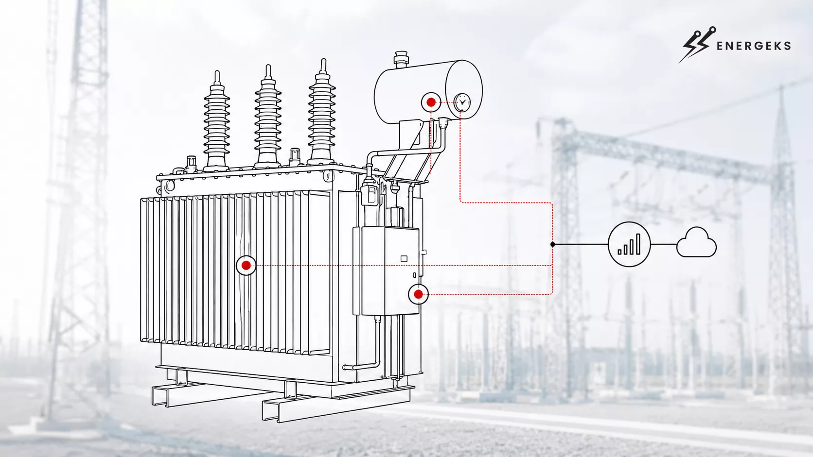
Online transformer monitoring is a solution particularly useful in industrial plants, power substations, photovoltaic farms, data centres and anywhere a transformer failure could stop a critical process. This article shows why to monitor a transformer online, which parameters matter most, and how to approach the topic for an entire fleet of devices. Special attention is given to temperature, moisture and load, because these three areas reveal a great deal about the actual operating conditions of a transformer.
Your transformer can operate for years without drawing particular attention to itself.
It stands in the substation, supplies a plant, a photovoltaic farm, a logistics centre or a bank of chargers.
It emits a characteristic, steady sound, its enclosure remains closed, and the operator checks on it during inspections and maintenance rounds.
Everything seems to be in order.
Inside, however, processes are constantly taking place that are invisible to the naked eye. Insulation ages under the influence of temperature. Load changes depending on the time of day and the nature of the installation's operation. Moisture can migrate between the oil and the cellulose insulation. The cooling system can gradually lose efficiency. A single deviation often does not yet indicate a serious problem, but a repeating trend should already interest those responsible for maintaining the device.
Transformer failure rarely comes out of nowhere. It usually sends warning signals beforehand. They just need to be collected, compared and properly interpreted.
That is what online transformer monitoring is about.
Energeks supplies medium‑voltage transformers – from the perspective of a manufacturer and supplier of energy solutions, we know that handing over a device for operation closes one stage of work.
After that, daily reality begins: variable loads, high ambient temperatures, operation in confined spaces, overloads, and decisions often made under time pressure.
Online transformer monitoring allows continuous tracking of temperature, load, moisture, oil level and other operating parameters. By analysing data in real time, it is possible to detect overloads, overheating, cooling problems and signs of insulation ageing earlier, reducing the risk of failure and unplanned downtime. In this article, we take a closer look at this topic.
Reading time: about 15 minutes.
Online transformer monitoring means continuously observing the device during its normal operation. The transformer does not need to be switched off, opened or visited by a technician every time we want to check what is happening with it. Sensors collect data, the system transmits it to the appropriate software, and the operator receives a picture of the device's operation along with history, trends and alarms.
It sounds simple, but in practice it is about much more than displaying a few numbers on a screen.
A transformer operates under changing conditions. In the morning, the load may be low; at midday, the plant starts up additional production lines; in the evening, power consumption drops again. In the case of a photovoltaic farm, the situation depends on insolation. In a logistics centre, the warehouse work rhythm matters, and for electric vehicle charging infrastructure, the load can increase sharply within a few minutes.
At the same time, oil temperature, ambient temperature, current flowing through the windings and the load on the cooling system change. If moisture, dirty radiators, unbalanced phase loading or deteriorating insulation condition are added to this, a single reading ceases to be sufficient. A history of the device's operation is needed.
And that history is what online monitoring creates.
Oil temperature shows how the transformer handles heat
Oil temperature is one of the most important parameters observed in oil‑immersed transformers. The oil insulates the live parts and removes the heat generated during core and winding operation. In short: the transformer produces heat, and the oil helps to carry it out of the device.
If the transformer operates under higher load, losses increase and oil temperature begins to rise. The phenomenon itself is completely normal. Concern arises when the temperature rises too quickly, persists for a long time, or reaches higher values than previously at similar operating conditions.
Let us imagine a transformer that operated for several months at a 70% load and maintained an oil temperature of around 55–60°C. If, after some time, at the same load, the temperature starts to reach 68–70°C, the system gives the maintenance team a very clear signal. The cause could be a dirty radiator, restricted oil flow, a fan problem, higher ambient temperature or changed installation conditions.
Without a history, such a reading is just a number. With a history, it becomes diagnostic information.
The duration of elevated temperature is also important. A fifteen‑minute load peak and eight hours of operation at high temperature have completely different implications for the insulation. Monitoring records both events and allows the actual operating profile to be reconstructed.
Winding temperature and the hottest point
Oil temperature says a lot about the conditions inside the tank, but it does not always show the hottest point in the transformer. Local areas of higher temperature, known as the hottest point, can occur in the windings.
The temperature of the hottest point is of great importance for assessing insulation ageing. Insulation materials do not age uniformly throughout the device. The most thermally stressed sections operate under more difficult conditions than areas where the temperature remains lower.
Depending on the transformer construction, the winding temperature or hottest point can be measured directly or determined based on oil temperature, load current and the device's thermal model. In both cases, the system needs data from several areas for the interpretation to make sense.
If the oil temperature looks correct but the model indicates an unusually high hottest‑point temperature, the team can check the load distribution, cooling condition and operating conditions. Such information is particularly valuable for devices operating close to their rated power limit.
The transformer does not have to trip immediately due to elevated temperature. However, the insulation can age faster, and subsequent overloads will gradually reduce the safety margin. Monitoring allows this process to be observed, rather than learning about it only after a failure.
Ambient temperature gives readings the right context
Ambient temperature may seem like a secondary parameter. In reality, without it, it is difficult to properly assess the cooling system's performance.
A transformer operating at an ambient temperature of 12°C has completely different heat dissipation conditions than a device located in a hot hall or container where the temperature exceeds 35°C. The same oil temperature can mean normal operation in one case and thermal overload in another.
High ambient temperature reduces cooling capacity. If the transformer is additionally located in a room with limited ventilation, heat can accumulate around the tank. Under such conditions, the device will heat up faster and return to its steady temperature more slowly.
Combining ambient temperature with oil temperature and load allows an assessment of whether the transformer's response is adequate to the conditions. The system can also capture seasonal changes. In summer, temperatures will be higher, in winter lower, but the device should behave according to a predictable pattern.
Current and voltage show the actual electrical conditions
Current monitoring allows checking how much energy is actually flowing through the transformer. The design documentation shows the rated power and expected operating conditions. Only operational measurements show what daily operation looks like.
Current can change very quickly. In a production plant, it increases when machines and production lines start up. In an installation with many inverters, it depends on energy production and load operation. In electric vehicle charging infrastructure, several simultaneous charging sessions can cause a short but intense peak.
The system records such events and allows determining whether they occur sporadically or repeat every day.
Voltage provides further information. Its fluctuations, asymmetry or unusual values may indicate problems in the grid, incorrect load configuration or conditions affecting the transformer load. When analysing voltage, power quality, harmonics and short‑term disturbances can also be considered.
Not every installation requires such an extensive power quality analysis. In the case of a plant with many drives, rectifiers, inverters and converters, however, such a measurement range can provide very important information about the transformer load.
Active and reactive power help understand the load character
Current alone tells you how much energy is flowing through the device. Active and reactive power help understand how that energy is being used.
Active power is responsible for the actual work of the loads: driving motors, powering machines, lighting, heating or charging batteries. Reactive power is associated, among other things, with the operation of inductive and capacitive devices. It does not perform useful work in the same way as active power, but it affects the current flowing in the installation and the transformer load.
In a plant, it may turn out that active power remains at a moderate level, but reactive power is high. The transformer must then conduct a higher current, which translates into losses and heating.
Monitoring allows these relationships to be observed over time. It can be checked whether specific devices or processes cause an increase in reactive power, whether the problem appears at a particular time, and whether compensation measures bring the expected effect.
Power factor shows how efficiently the infrastructure is being used
The power factor, denoted as cos φ, describes the relationship between active power and apparent power. The lower its value, the greater the share of reactive power in the total electrical load.
A high power factor means more favourable utilisation of the transformer's available capacity. A low power factor can cause current to increase, losses to rise and the available load margin to be reduced.
For a fleet operator, cos φ data can be useful when comparing locations. One plant may draw a similar active power to another, yet load its transformer more heavily due to a higher share of reactive power.
This type of information helps in making decisions regarding reactive power compensation, load distribution and future installation expansion planning.
Load imbalance between phases
In an ideal world, each phase would be loaded evenly. In real installations, however, loads are distributed differently, some operate cyclically, and some start up independently.
If one phase is significantly more loaded than the others, uneven heating and worsening operating conditions can occur. Long‑term asymmetry also affects voltage quality and can be a signal of a problem on the load side.
Monitoring each phase allows you to see whether the imbalance is temporary or permanent. In the first case, it may result from a normal work cycle. In the second, it is worth checking the load distribution, installation configuration and devices connected to individual phases.
This is particularly important in large plants where load changes with the operation of many independent loads.
Oil level and system tightness
In an oil‑immersed transformer, the oil level is directly related to insulation safety and cooling. A drop in level may result from a leak in the tank, pipes, bushings, radiators or the conservator system.
A small change does not always mean an immediate threat. If the level gradually drops over several weeks, the system can help determine the rate of loss. If the drop is sudden, the alarm should prompt a rapid inspection.
The influence of temperature is also important. Oil changes volume with temperature, so its level can naturally differ depending on operating conditions. Monitoring allows the oil level to be correlated with temperature and distinguishes normal volume change from a potential leak.
For transformers equipped with a conservator, level indicators and the breathing system play an additional role. Data from these elements can complement the picture and help assess whether the device is behaving correctly.
Moisture in oil and insulation
Moisture has a significant impact on the condition of a transformer's insulation system. It can accelerate paper ageing, reduce the dielectric strength of the oil and affect the device's behaviour under higher load.
Sources of moisture can include leaks, the breathing system, seals, transport conditions, storage and servicing. Water can also migrate between the oil and the cellulosic materials inside the transformer.
Interpreting the measurement requires taking temperature into account. Moisture is not distributed in the insulation in a completely static way. When temperature and load change, the equilibrium conditions between oil and paper also change.
Therefore, moisture monitoring is most valuable when data is analysed together with oil temperature, hottest‑point temperature and load. Then it is possible to observe whether the moisture level is stable, increasing, reacting to overloads or showing seasonal changes.
Gases dissolved in the oil
Gases dissolved in the oil are produced by processes occurring inside the transformer. Their presence does not always mean a serious fault, but specific gases and their rate of increase can indicate overheating, partial discharges, cellulose degradation or arcing.
DGA analysis can be performed in a laboratory based on oil samples. For transformers of high power or high criticality, an online analyser can be used to continuously monitor selected gases.
Such a system does not replace the laboratory or the engineer's experience. It does, however, provide information between successive tests. If the concentration of a particular gas starts to rise faster than before, the operator can plan additional testing, load reduction or device inspection.
In transformer diagnostics, the rate of change is of great importance. A single result can be difficult to interpret. A series of results showing a clear trend tells much more.
Fan and pump condition
The cooling system may have a very good design and adequate capacity, but its effectiveness depends on the actual operation of fans, pumps, thermostats, controllers and the power supply system.
Monitoring can show when fans were started, how long they have been running and whether the temperature changes as expected. If the fans run for a long time and the oil temperature continues to rise, the causes should be sought more broadly. There may be a problem with airflow, a dirty radiator, an oil pump or a sensor.
For a fleet of transformers, comparing cooling operation can be very interesting. If one transformer, at a similar load, starts its fans significantly more often than the others, the system shows a difference worth investigating.
Vibration and unusual noise
A transformer emits a characteristic sound related, among other things, to core operation, magnetostriction and load current. A change in noise or the appearance of unusual vibrations may indicate mechanical problems, loose elements, a change in core operation or abnormalities in the windings.
Noise alone is difficult to assess solely on the basis of subjective human perception. One operator may say the transformer "is humming a bit louder", another may consider everything normal. Vibration sensors and frequency analysis allow the current signal to be compared with previous measurements.
Not every change in sound means damage. What counts is repeatability, the direction of the change and consistency with other parameters.
Partial discharges
Partial discharges are local electrical phenomena occurring where the insulation is not working correctly. They may be associated with voids, contamination, damage to the insulating material or local overstressing of the electric field.
Their detection requires appropriately selected sensors and advanced interpretation. Partial discharge monitoring is used primarily for devices of high value, great importance to the system or with an increased risk of failure.
Early detection of such phenomena allows more detailed diagnostics and planning of actions. For a transformer supplying a critical industrial process, this can determine whether a shutdown takes place during scheduled downtime or in the middle of normal production.
Protection alarms and event history
Monitoring should also record alarms and protection operations. The information that an alarm is active is important, but the history is even more valuable.
It is possible to check whether the alarm appears for the first time or has been recurring for several months. It can be correlated with temperature, load and cooling status. It can be seen whether, after a specific event, the parameters returned to their previous level.
Thanks to this, every event is recorded and can be used in subsequent analyses. The device's memory does not depend on whether someone happened to be on site and wrote down the result in a notebook.
Not every transformer needs an extensive system with gas analysis, vibration and partial discharge monitoring.
A small distribution transformer working in an easily accessible hall may require monitoring of temperature, load and basic alarms. For a larger unit supplying a production line, oil level, cooling status and trend analysis should be added. A transformer operating in a hospital, data centre, steelworks or large power substation may require a much wider diagnostic scope.
The device's power, age, operating history, load character, reserve availability, delivery time for a new transformer, environmental conditions and the cost of downtime should all be considered.
For a fleet, a tiered model is particularly useful. The most important devices receive extensive monitoring, while the others are observed using a basic set of parameters. All data, however, goes to a common system, allowing comparison of individual units and quick identification of devices behaving differently from the rest.
Online monitoring makes sense when the data leads to action. The operator should know what an alarm means, who analyses it and what steps to take. Then the sensors, communication and software form a practical maintenance tool, rather than another tab in a system that no one looks at.
Protections are essential.
They protect the transformer and the installation in situations where continued operation could lead to serious damage. They respond to specific fault conditions: short circuits, overloads, excessive temperature, oil level drop or other dangerous phenomena.
Their action is of an interventionist nature.
Monitoring provides a broader picture.
It records operating conditions before, during and after an alarm. It shows not only that the temperature exceeded a certain level, but also whether similar events have occurred over recent weeks. It can be checked at what load the problem appears, how quickly the temperature rises and whether the cooling system responds correctly.
A transformer can operate for a long time under conditions that do not immediately trigger a protection. Regular overloads, insufficient cooling or elevated moisture can gradually degrade the insulation. The device still supplies the loads, but its safety margin becomes smaller and smaller.
These are precisely the processes that are particularly important from the point of view of online monitoring. They allow a response to a change in the device's behaviour before the situation reaches a level requiring emergency shutdown.
Temperature is one of the easiest parameters to measure and one of the most useful diagnostic indicators.
In an oil‑immersed transformer, the oil insulates the windings and removes heat from them. Energy lost in the core and windings is converted into heat, which must be transferred to the surroundings. At higher load, losses increase and temperature rises with them.
The temperature rise itself during higher load is a natural phenomenon. What matters is how the device responds to changing conditions.
Suppose the transformer on Monday operated at 70% load and the oil temperature stabilised at 58°C. A week later, at a similar load, the temperature rose to 66°C. This does not yet mean a failure, but it is information that requires checking. The cause could be higher ambient temperature, a dirty radiator, restricted oil flow, a fan problem or changed installation conditions.
Monitoring allows the following to be correlated:
load,
oil temperature,
ambient temperature,
duration of elevated temperature,
cooling system status,
history of previous measurements.
Such a data set gives a much more complete picture than a single reading taken during a technician's visit.
High temperature accelerates insulation ageing. Every transformer has specified operating conditions, but long‑term operation at elevated temperature can shorten its actual life. Therefore, the system should also record the duration of load and temperature. A short‑term load peak and many hours of operation at high temperature have different implications for the device.
Both measurements are needed because they show different elements of the same process.
Oil temperature indicates the thermal conditions in the tank. Winding temperature or the calculated hottest‑point temperature allows better assessment of the insulation load and local heating.
In many transformers, the hottest‑point temperature is not measured directly. It is determined based on oil temperature, load current, device characteristics and a thermal model. In more advanced systems, additional sensors or solutions for more accurate winding condition assessment can be used.
The hottest point is particularly important because the local temperature can be higher than the value read elsewhere in the tank. It is in the hottest fragments that insulation ages faster.
If the monitoring system knows the oil temperature, load and ambient conditions, it can assess whether the current operation is within the expected thermal profile. A deviation from this profile may indicate a change in cooling efficiency, a mechanical problem or an unusual load distribution.
A transformer operates under conditions that can change very dynamically.
In a production plant, load increases when machines are started. In an automated warehouse, it depends on the intensity of transport system operation. In a facility with car chargers, power consumption can change depending on the number of vehicles charging simultaneously. On a photovoltaic farm, load and energy flow depend on inverter production and grid configuration.
Design assumptions about average power consumption may look reasonable on paper, but actual operation can bring a completely different profile.
Load monitoring shows:
when peaks occur,
how long they last,
how often they repeat,
whether the load is balanced between phases,
how the transformer responds thermally,
whether seasonal overloads appear.
For example, a transformer may have an average load of 65%, yet operate at 105% for two hours every day. The daily average looks safe, but the recurring peaks affect temperature and insulation ageing.
An additional issue is phase asymmetry. Uneven loading can lead to local temperature rises and worsen operating conditions. Monitoring each phase allows you to see that the problem concerns a specific part of the installation, not the entire transformer.
Moisture affects the oil, paper insulation and the overall strength of the insulation system.
It can enter the transformer through leaks, the breathing system, damaged seals, incorrectly performed service work or improper transport and storage conditions. Water can also be generated or migrate within the insulating materials during operation.
Cellulosic insulation absorbs moisture. Its presence can accelerate paper degradation, reduce the dielectric strength of the oil and increase the risk of adverse phenomena during overload. At high temperature and with the right moisture concentration, the risk of gas bubble formation in the oil can also arise.
Moisture does not behave in a completely static way in a transformer. Its distribution depends on temperature, load, oil type and insulation condition. Water can migrate between oil and paper. The result of a sample taken at one moment does not always reflect the full state of the entire insulation system.
Therefore, moisture monitoring should be analysed together with temperature and load. Only then can it be seen whether a particular change is a permanent trend, a reaction to a change in operating conditions or the result of a measurement error.
CIGRE indicates that when interpreting moisture, factors such as oil temperature, hottest‑point temperature, load, cooling mode and breathing system type should be considered. This approach allows better assessment of insulation ageing and overload risk.
You may also be interested in this topic:
Water vapour condensation in a transformer tank. The silent killer in winter.
Gases can accumulate in transformer oil as a result of processes occurring inside the device. Their type, concentration and rate of increase provide information about potential problems.
DGA analysis includes, among others, hydrogen, methane, ethane, ethylene, acetylene, carbon monoxide and carbon dioxide. Individual gases can be associated with oil overheating, cellulose degradation, partial discharges or arcing.
Traditional laboratory analysis involves periodic oil sampling. This is an important diagnostic method and remains the basis of many transformer maintenance procedures. Online monitoring allows changes between laboratory tests to be observed.
For a large transformer operating in a critical installation, continuous gas analysis can be particularly important. A rapid increase in a specific component can trigger additional inspection, sampling, load reduction or planned shutdown preparation.
DGA requires expert interpretation. It is not enough to look at one number and decide to replace the device immediately. The history, rate of change, gas ratios, laboratory results, temperature, load and other symptoms are analysed.
Gas laws in DGA: 5 physical rules that warn you before a transformer failure occurs
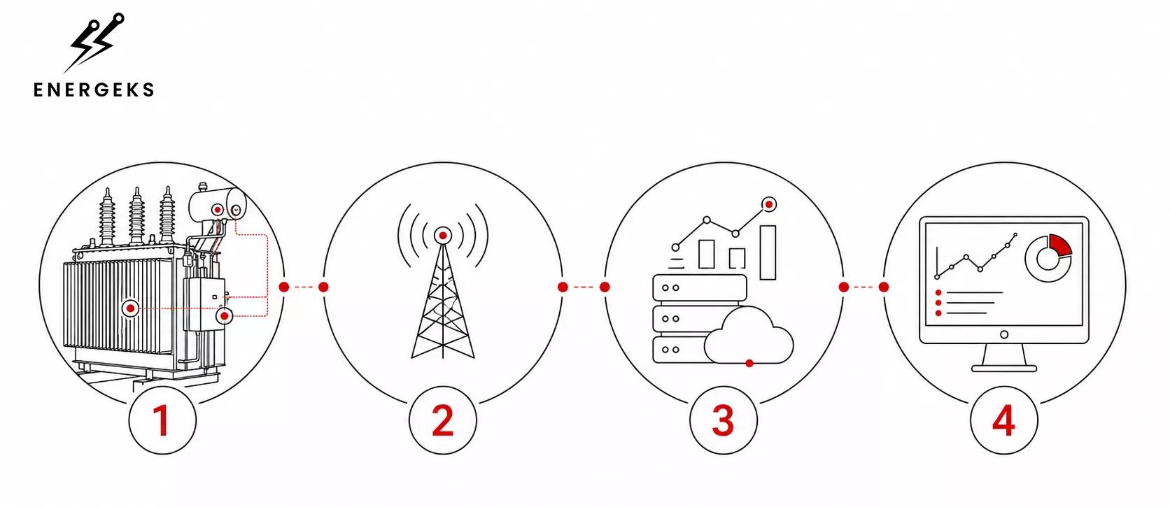
A monitoring system consists of several cooperating layers.
The first is the sensors. They record temperature, current, voltage, moisture, oil level, gases or vibration.
The second layer is responsible for data collection and transmission. A communication module or industrial gateway can perform preliminary processing of measurements, filter interference, store data locally and transmit it to the supervisory system. Depending on the infrastructure, Ethernet, Modbus TCP, MQTT, cellular network or integration with a SCADA system are used.
The third layer covers analysis. The software compares values with alarm levels, tracks trends and can detect deviations from the typical behaviour of a specific device.
The fourth layer is for presentation and alarm handling. The operator can receive information on a panel, by email, SMS or in an application. For distributed installations, remote access is particularly important.
The greatest value comes from a system that delivers information understandable to the maintenance team. An alarm should indicate the device, the parameter, the time the problem started, the rate of change and the urgency level.
The first layer of the system is located directly at the transformer. Sensors record its key operating parameters: oil and winding temperature, current, voltage, load, moisture, oil level, dissolved gases and vibrations. This is where the data reflecting the actual condition of the equipment is generated.
2. Data collection and transmission
The collected measurements are sent to a communication module or industrial gateway. The device can initially filter out interference, store data locally and transmit it via Ethernet, Modbus TCP, MQTT, a cellular network or an existing SCADA system.
3. Analysis and interpretation
In the third layer, the data begins to provide meaningful information. The software compares current readings with alarm thresholds, analyses trends and checks whether the transformer is behaving in the same way as before. The system can detect a gradual rise in temperature, unusual loading or a change in parameters that has not yet exceeded the alarm threshold.
4. Presentation and response
The final layer delivers the information to the operator. Results can be displayed in a dashboard, application or SCADA system, or sent by email, SMS or push notification. An effective alarm identifies the specific unit and parameter, the moment the issue began, the rate of change and the level of urgency. This allows the team to determine whether observation is sufficient, additional diagnostics are required or immediate action must be taken.
For a larger number of devices, online monitoring helps organise a huge amount of information.
For a single transformer, regular rounds, oil tests, thermography and inspections can provide sufficient control. For a dozen or several dozen units, the risk increases that the team will miss a change developing between visits.
The fleet may be dispersed across plants, substations, PV farms and charging points. Each transformer may have a different power, age, operating history and process significance. A central system allows information to be gathered in one place.
The operator can check the condition of the entire fleet and then go to a selected location and specific device. It is possible to compare transformers of similar power and construction. It is visible which devices have the most alarms, which operate closest to the load limit and where the temperature rises faster than in comparable units.
Such a system also helps to identify problems common to several devices. If transformers from the same location have similar temperature profiles, the cause may be the ventilation method, ambient temperature or installation conditions. If only one unit behaves differently, its individual technical condition is more likely to be the issue.
For a larger number of devices, online monitoring helps organise a huge amount of information.
For a single transformer, regular rounds, oil tests, thermography and inspections can provide sufficient control. For a dozen or several dozen units, the risk increases that the team will miss a change developing between visits.
The fleet may be dispersed across plants, substations, PV farms and charging points. Each transformer may have a different power, age, operating history and process significance. A central system allows information to be gathered in one place.
The operator can check the condition of the entire fleet and then go to a selected location and specific device. It is possible to compare transformers of similar power and construction. It is visible which devices have the most alarms, which operate closest to the load limit and where the temperature rises faster than in comparable units.
Such a system also helps to identify problems common to several devices. If transformers from the same location have similar temperature profiles, the cause may be the ventilation method, ambient temperature or installation conditions. If only one unit behaves differently, its individual technical condition is more likely to be the issue.
Fleet monitoring begins with a simple question: which devices really require constant attention, and which can operate calmly under basic supervision?
Because if we connect all possible sensors to every transformer, we will create an impressive amount of data. But what good is it if the operator has to look at hundreds of charts every day, most of which change nothing? The monitoring system is meant to help make decisions, not to give the maintenance team a digital marathon through dashboards.
A well‑designed fleet monitoring system should correspond to the infrastructure management structure. The person responsible for the entire energy asset needs a different view than a technician analysing a specific transformer. One looks at the whole map, the other looks into the details of a specific device.
Three levels of information
At the highest level, the manager should see the entire fleet quickly and clearly. How many transformers are operating correctly? Where have active alarms appeared? Which locations require a response? Does the problem concern one device, or perhaps several transformers operating under similar conditions?
Such a view should not resemble the cockpit of an aircraft preparing for a Mars landing. A clear location map, device status, number of alarms, urgency level and information on which units deviate from their typical behaviour are enough.
If ninety‑nine transformers are operating stably and one has been showing elevated temperature at similar load for several days, the system should bring that information to the foreground. The operator should not have to search for it among hundreds of green indicators. Green is pleasant, but in excess it can effectively hide a small red problem.
The second level concerns a specific substation, plant or location. Here, the mutual operation of several devices matters. Their load, temperatures, cooling system activity and alarm history can be compared. Such a view helps to see whether the load is distributed evenly and whether one transformer is not taking on too much of the work.
For example: three transformers in a plant operate at a similar ambient temperature. Two maintain an oil temperature of 55°C, and the third reaches 68°C at a similar load. This is not yet a ready technical verdict, but it is a very good reason to check the cooling, airflow, radiator dirt, sensor readings and actual operating conditions.
At the third level is the specific transformer. Here, details are needed: temperature, current and load charts, oil level data, moisture, fan operation, oil test results, inspection information, reported faults and a history of actions taken.
A technician should be able to check not only that an alarm occurred, but also when it started, how long it lasted and what was happening with the device at the same time. An alarm without context resembles a message: "something is wrong." The history already allows a specific question: what exactly changed and what could have caused that change?
First criticality, then sensors
Before selecting the scope of monitoring, a criticality analysis of each transformer should be performed. It sounds very formal, but in practice it is about determining how much a given unit can make life difficult for the company if it suddenly stops working.
Does the transformer supply one hall or an entire production line? Will its failure stop a technological process, a server room, a cooling system or charging infrastructure? Is there a backup transformer? How long would it take to deliver a new device? Can it be brought in without rebuilding the foundation and the entire installation?
Location should also be considered. A transformer located at a plant with 24/7 service availability is in a different situation than a device operating at a remote photovoltaic farm, in difficult terrain or in a substation that requires planning and outages to access.
History also matters. If the device previously had problems with temperature, moisture, leaks, the tap changer or the cooling system, it should not be treated the same as a new transformer that has been operating stably for years.
Add to this the cost of downtime. In one place, an hour‑long interruption means a few phone calls and a shift in the work plan. In another, it can mean production stoppage, loss of a batch of material, interruption of energy supplies or the need to start expensive backup power.
Not every transformer needs the same monitoring
After the criticality analysis, transformers can be divided into several groups.
The most important units receive extensive monitoring. For them, observation of oil and hottest‑point temperature, load, oil level, moisture, cooling status and protection alarms can be justified, and with sufficiently high power, also dissolved gases, vibration or partial discharges.
The second group includes devices important to the process but with partial reserve or easier service access. Here, monitoring of temperature, current, voltage, load, basic alarms and cooling operation may be reasonable. If the data shows a worrying trend, diagnostics can be expanded or additional tests planned.
The third group consists of units of lower criticality, operating under predictable conditions and easily accessible to personnel. In such cases, basic parameter monitoring, an alarm register and periodic trend analysis are often sufficient.
This approach helps avoid two extremes. The first involves equipping every transformer with the entire diagnostic catalogue, even though no one subsequently analyses the data obtained. The second reduces monitoring to a single indicator that lights up green for five years until one day it goes out together with the transformer.
Comparison matters, not just the number
For a fleet, the ability to compare devices is particularly valuable. A transformer should not be evaluated solely by a single universal limit. It is worth checking how it behaves relative to its own history and relative to similar units.
If all transformers in a given group respond similarly to a rise in ambient temperature, we are probably dealing with a normal phenomenon. If one of them starts heating up faster than the others, the situation is different.
The same applies to alarms. Two devices may have five alarms per month, but in one case they will be short warnings related to a temporary load peak, and in the other, repeating signals about rising temperature and cooling problems. The number of alarms alone is not enough. Their context, duration and correlation with other parameters are needed.
Monitoring must end with a decision
The best monitoring system is not the one that shows the most data. It is the one that helps decide what to do next.
An alarm should have a defined urgency level. For an informational signal, recording the event and observing the trend is sufficient. A warning may require analysis by the maintenance team or planning an additional measurement. A critical alarm should trigger a clearly defined procedure: load reduction, on‑site inspection, preparation for shutdown or switching to reserve.
Each alarm should indicate the specific device, the parameter, the time the problem started, the rate of change and the conditions under which it occurred. It is good if the system also suggests what actions were taken previously and whether a similar situation has occurred in the past.
Transformer fleet monitoring should therefore work like a well‑organised team. At the top, it shows a picture of the entire infrastructure. Lower down, it allows analysis of a specific substation. At the end, it leads the technician to one device, one trend and one decision.
Online monitoring should work alongside existing diagnostic methods.
Visual inspection allows assessment of the tank, connections, bushings, radiators, valves and seals. Thermography shows the temperature distribution on the device surface. Oil tests provide information about its properties, water content, dielectric strength and dissolved gases. Electrical measurements allow assessment of selected elements of the insulation system.
A temperature sensor will not replace visual inspection. A monitoring platform will not perform a connection assessment for the technician. Online DGA does not eliminate the need for laboratory tests, especially when a worrying change appears.
The best results come from combining current data with documentation, the device's history and inspection results. Then it is possible to determine whether the current deviation is something new or has been recurring for some time.
First, it must be determined what problem the system is intended to solve. In one plant, the most important factor will be overload control. In another, remote observation of dispersed devices will be a priority. For a large grid transformer, dissolved gases, moisture and hottest‑point temperature may be relevant.
Next, sensors, communication methods and the extent of integration with the existing automation system are selected. At this stage, it is worth checking which signals are already available and which require additional instrumentation.
After commissioning, the system should collect baseline data. A few weeks of normal operation help establish the typical temperature, load and cooling profile. Only on this basis can alarms be properly tuned.
The next element is the response procedure. Each alarm should have an assigned responsible person and a defined course of action. The team should know when observation is sufficient, when an additional test is needed and when the load should be reduced or a shutdown prepared.
A monitoring system without a response procedure remains merely a source of data. Its value appears when the data leads to a specific operational decision.
Cost‑effectiveness depends on the relationship between the implementation cost and the consequences of a failure.
Downtime can mean production stoppage, loss of energy sales opportunities, problems with contract fulfilment, costs of renting a replacement transformer, transport, service work and restarting the installation.
Monitoring is particularly well justified for transformers:
supplying critical processes,
operating under high or variable load,
located in difficult‑to‑access locations,
belonging to a dispersed fleet,
whose replacement involves a long delivery time,
with a history of faults,
lacking a backup unit.
For a smaller transformer of low criticality, basic temperature, current and alarm monitoring may be sufficient. For a large device operating in a key substation, the diagnostic scope will be much wider.
The best basis for a decision is a risk analysis. The price of the system should be compared with the value of the protected process and the possible cost of downtime.
For most installations, a good starting point is temperature, load and cooling system status.
Temperature shows the thermal operating conditions of the transformer. Load explains what these conditions result from. The status of fans, pumps and other cooling elements allows assessment of whether the device is properly dissipating heat.
For oil‑immersed transformers, oil level and moisture monitoring should also be considered. For units of high power or criticality, online DGA, partial discharge measurement and vibration analysis may be justified.
The choice should result from the device's construction, operating method and the consequences of a potential failure. Each additional function makes sense when the data will be used in the maintenance process.
Online transformer monitoring provides the ability to observe the device during actual operation. It shows temperature, load, moisture and other parameters over time, making it possible to identify trends and respond to changes early enough.
For a single transformer, the system helps organise diagnostics and reduce the risk of missing a problem. For an entire fleet, it becomes an energy asset management tool. It facilitates comparing units, setting priorities, planning inspections and making decisions about further operation.
A transformer can operate correctly for many years, but its condition changes with temperature, load, moisture and environmental conditions. The more we know about these changes, the easier it is to plan service, reduce downtime and use the device safely.
Energeks supplies oil‑immersed and cast‑resin transformers, selected for the actual load, operating conditions and installation significance. When choosing a device, requirements regarding cooling, resistance to moisture and dust, fire safety, noise level, available space and the planned monitoring system can be taken into account.
If you are interested in solutions available off‑the‑shelf, explore the range of transformers currently in stock at Energeks.
Also join us on LinkedIn, where we are building a community of power engineering enthusiasts and professionals. Thank you and see you there!
Sources:
CIGRE – Online moisture monitoring of transformers for ageing assessment
IEC – The Establishment and Design of Standard for Condition Monitoring in Power Systems
Hitachi Energy – TXpert Ready CoreSense M10 online DGA analyzer
Shipped from our warehouse in Poland within 2–3 working days, 5-year warranty. Full range 25–2500 kVA in the shop (prices in PLN).
No reviews!