5 Aug
2026
Energeks
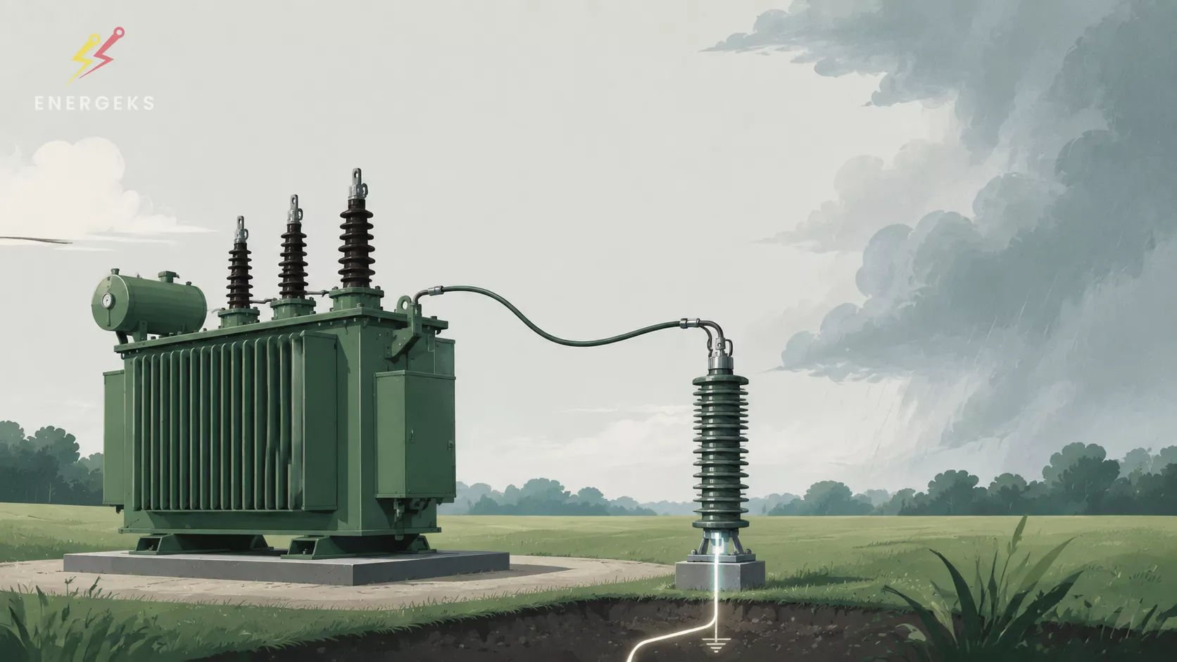
Heat melts people. Thunderstorms test transformers.
And it does it in microseconds.
The heatwave season has its own physics. The air stands still, asphalt softens, and we all slowly change our state of matter. A person starts treating shade like premium real estate, and every fridge opening sounds like a strategic decision.
And then the storm comes.
For a moment, it brings relief. The temperature drops, the wind picks up, the air regains its meaning. Except that for the power grid, that same storm is not a pleasant break from the heat. It is a test whose outcome can be decided in less time than a blink of an eye. Much less.
0.000001 seconds. That is how long one microsecond lasts.
It is on this scale that the front of a lightning surge develops. Does the transformer have a chance to survive it? Yes, provided that the right decisions were made before the first flash appeared in the sky.
The overvoltage reaching the transformer develops in microseconds. The operator will not have time to react. The controller will not call a meeting. The transformer also does not have a moment to "prepare" its insulation. The outcome is decided by solutions chosen earlier: insulation coordination, the type and parameters of the surge arrester, its location, the length of the connections, and the quality of the entire surge current discharge path.
This is why lightning protection for a transformer is a good topic right now. Not because a thunderstorm is spectacular, but because it reminds us of a simple rule in power engineering: the most important protections do their work when no one has time left to make a decision.
A lightning strike does not have to hit the transformer directly to cause a dangerous overvoltage. A surge can enter the system through several paths.
A direct strike on an overhead line introduces a very high current with a steep change over time. A strike near the line can induce voltage in the conductors. Another possibility is a strike to a structure, a lightning protection system or the ground, which causes a sudden change in the potential of the earthing system. A surge wave can also arrive from another part of the grid, travelling along conductors and cables.
The transformer therefore sees not so much the flash itself, but the voltage wave appearing at its terminals.
If the value and steepness of this wave exceed the insulation's ability to withstand the electrical stress, a flashover on the bushing, breakdown of the main insulation or damage to the turn‑to‑turn insulation can occur. Not every event ends with an immediate short circuit. Sometimes the impulse leaves behind a weakening, local damage or the beginning of a degradation process that will manifest itself later.
This is precisely why the absence of a failure immediately after a storm is not automatically proof that the protection system worked perfectly. Insulation can remember electrical stress, even though it does not keep an event log.
In high‑voltage engineering, the resistance of equipment to atmospheric overvoltages is assessed, among other things, using a standardised voltage impulse. The designation 1.2/50 µs describes a waveform whose nominal rise time is 1.2 microseconds and whose time to fall to half the value is 50 microseconds.
This is a test model, not a photographic portrait of every lightning strike. It does, however, allow the insulation strength of equipment to be compared and consistent principles of insulation coordination to be established.
One microsecond is one millionth of a second. In 1.2 microseconds, an electromagnetic wave can travel hundreds of metres, depending on the propagation medium. From a human perspective, nothing has happened yet. From the transformer's perspective, the voltage has already reached a level that can determine the fate of its insulation.
The steepness of the impulse is as important as its peak value. For fast‑changing currents, every fragment of conductor has inductance. The voltage on such a connection can be described by the relationship:
UL = L × (di / dt)
The faster the current rises and the greater the inductance of the connection, the greater the additional voltage drop. This voltage can add to the residual voltage of the arrester and appear at the terminals of the protected device.
The example is illustrative. If the connection has an inductance of about 1 µH and the surge current changes at a rate of 10 kA/µs, the connection itself can contribute about 10 kV. This does not mean that every metre of conductor always "costs" exactly 10 kV. It does, however, show the scale of the phenomenon and explains why, in surge protection, a short path is an electrical parameter, not an installer's aesthetic preference.
Yes, but not by itself and not against every scenario.
The external lightning protection system is designed to intercept a direct strike on the protected structure, conduct the current along a designated path and disperse it into the ground. It thus limits the risk of physical damage to the structure and the danger to people. The scope of this protection is described by the IEC 62305 series.
A surge arrester works on a different part of the problem. Its task is to limit the overvoltage on the device and direct the surge current to the earthing system. In medium‑voltage networks, it protects, among other things, transformers, bushings and switchgear against atmospheric and switching overvoltages.
Insulation coordination connects both worlds with the transformer itself. It consists of selecting the insulation strength, the protection level of the arresters and the system configuration so that the stress reaching the device remains below its assumed withstand level, with an appropriate margin.
So you can build a correct lightning protection system for the building and still leave the transformer with insufficient protection against a wave arriving via a conductor. You can also choose a good arrester and weaken its effectiveness with excessively long connections. Protection works as a system. The logo on one component does not replace the physics of the entire surge path.
In modern AC networks, gapless metal‑oxide surge arresters with metal‑oxide resistors are widely used. Their requirements are specified in IEC 60099‑4 for systems with the highest voltage for equipment above 1 kV.
In everyday language, they are often called lightning arresters. In industry jargon, the more precise term is surge arrester, because the device does not catch lightning like a baseball glove. It limits the voltage and creates a controlled path for the surge current. A small linguistic difference, perhaps, but behind it lies the entire principle of operation.
The heart of the arrester is a non‑linear block, most often based on zinc oxide. Under normal conditions, the arrester has a very high resistance and only conducts a small leakage current. When the voltage rises sharply, its characteristic changes dramatically. The arrester begins to conduct the surge current, directing it to earth and limiting the voltage on the protected device.
After the overvoltage subsides, it returns to a high‑resistance state. It does not "swallow" the entire lightning strike and does not make the voltage disappear. It limits it to a specific level, called the residual voltage or protection level, and absorbs and dissipates part of the energy.
The whole process involves the appearance of the overvoltage, the rapid increase in the arrester's conductivity, the discharge of the surge current and the device's return to a high‑resistance state. For it to actually protect the transformer, the residual voltage, together with additional drops on the connections, must remain safely below the impulse withstand voltage of the insulation.
Different constructions can be found on the market and in older installations. Not all of them should be lumped together in the same drawer.
The modern standard for transformer protection is gapless arresters with ZnO blocks. They react thanks to the strongly non‑linear characteristic of the material and can withstand successive surges within their declared capability.
Older spark‑gap constructions, often with silicon carbide resistors, are still operating in some facilities. When modernising, ZnO is usually considered, but a "one‑to‑one" replacement without checking the network parameters and insulation coordination is not a good shortcut.
There are also special solutions, for example arresters with an external spark gap used on lines, and constructions for GIS. Their application is determined by the function, the insulation system and the overvoltage analysis, not by a catalogue power ranking.
The most effective therefore does not mean the most impressive in the catalogue. It means properly selected for the voltage, the network earthing method, the expected energy, the transformer's LI level and the environmental conditions.
IEC 60076‑3 specifies the insulation requirements, dielectric tests and minimum test levels for transformers. The IEC 60071 series sets out the principles of insulation coordination for equipment and installations above 1 kV.
In design practice, at least two levels must be compared:
the rated lightning impulse withstand voltage of the transformer, often abbreviated as LI
the protection level provided by the arrester under specific current and impulse shape conditions
A margin should remain between them, taking into account uncertainties, the installation configuration, the distance from the transformer, the inductance of the conductors, wave phenomena and actual operating conditions.
It is not enough to check whether the number on the arrester data sheet is lower than the number on the transformer documentation. The voltage seen by the insulation can be higher than the residual voltage itself. Inductive drops and the effect of distance from the device must be added.
The shortest version of this rule is: the arrester does not protect the transformer's catalogue. It protects a specific transformer in a specific installation.
Selection begins with the system data, not with one voltage printed on the housing.
✅ Continuous operating voltage
The Uc value, i.e., the permissible continuous operating voltage, must correspond to the highest voltage that can occur on the arrester for a long time. The neutral earthing method and the voltage rise of healthy phases during an earth fault are important.
Too low a Uc can expose the arrester to overload during a temporary overvoltage. Too high a Uc usually means a higher protection level, which can reduce the margin for the transformer insulation.
✅ Rated voltage and temporary overvoltage withstand
The Ur and TOV parameters must be assessed together with the duration of the possible overvoltage. The arrester must survive a real fault scenario or other disturbance in the given network, not just the nominal operating point.
✅ Protection level
The residual voltage must be compared with the transformer's impulse withstand level. The influence of connections and location must also be taken into account. A low value in the table is useful only when the installation allows it to be exploited.
✅ Energy and charge capability
The exposure depends on the network configuration. Different requirements may apply to a station supplied by a long overhead line in an area of high lightning activity than to a device operating in a cable system. Switching overvoltages, the repeatability of surges and the nature of the protected facility also matter.
✅ Environmental and mechanical conditions
Altitude above sea level, pollution, UV radiation, temperature, humidity and mechanical loads influence the choice of design. The selection of a silicone or porcelain housing should result from the project conditions.
✅ Behaviour in the event of failure
The short‑circuit class, the method of safe venting or disconnection, and the risk to people and adjacent equipment must be considered. Protection of the transformer must not create a new problem at the moment when the arrester itself reaches the end of its service capability.
The best arrester placed too far from the transformer can provide weaker protection than a properly selected device mounted at the protected terminal.
Three principles decide:
the smallest possible distance between the arrester and the transformer bushing
short, straight connections on the phase and earthing side
avoiding loops, sharp changes of direction and unnecessary conductor sections
During surge current flow, the impedance of the entire path matters, not just the earthing resistance measured at power frequency or by a method suitable for static conditions. A fast impulse "sees" the inductance of the conductors, the geometry of the system and the mutual position of the connections.
Therefore, a larger conductor cross‑section does not automatically fix the problem of excessive length. Cross‑section remains important for thermal, mechanical and short‑circuit reasons, but for a very steep impulse, the path geometry can determine the induced voltage.
It is here that theory meets execution detail. An extra metre of conductor may look innocent. For an impulse measured in microseconds, it is a fully‑fledged circuit element.
A surge arrester does not remove energy from the system. It provides a controlled path for it. If this path has a high impulse impedance or is routed in a way that creates significant potential differences, the voltage on the protected device can still reach a dangerous level.
An effective system requires continuity of connections, correct connection of the transformer tank, the structure, cable screens and the other elements covered by the earthing design. Equipotential bonding is also important. During a discharge, the potential of the local earth electrode can rise sharply. The goal is not to magically keep the entire station at perfect zero potential, but to limit dangerous potential differences and ensure a predictable current path.
The earthing resistance value alone does not tell the whole story. Proper geometry, connections of adequate durability, corrosion control and compliance with the lightning protection design and network requirements are also needed.
Earthing is a bit like an evacuation route. Knowing that it exists is not enough.
It must lead where it should, be clear and work exactly when things get crowded.
No. It changes the risk profile but does not cancel it.
A cable is less exposed to a direct strike than an overhead line. A wave can, however, enter at the transition point from an overhead line, be caused by a rise in earth potential, or arrive from another part of the grid. Reflections at the boundaries of different impedances also change the voltage. Therefore, terminations, cable length, screens, earthing and surge limitation points must be analysed. A cable underground does not receive immunity from thunderstorms.
Is it enough to protect the MV side?
An arrester on the MV side protects the transformer against a wave arriving from that grid, but an impulse can transfer between windings. On the LV side, today there are controllers, inverters, measurements, communication and automation. Therefore, protection should be layered: include MV, coordinated SPDs on the LV side, auxiliary and signal circuits, and equipotential bonding. Protection of the transformer and of the electronics are related but not identical tasks.
A poorly selected arrester is a bit like a solid door installed next to the entrance.
It looks professional, but lightning has no obligation to use it.
❌ The first mistake is selection based solely on the rated network voltage.
Omitting the neutral earthing, the earth‑fault clearing time and TOV can give an incorrect Uc value. Too low a value exposes the device to overload, while too high a value can worsen the protection level.
❌ The second is installation far from the bushing.
In a surge, there is no such thing as "just a piece of conductor". Every section contributes inductance.
❌ The third is running long, looped connections to the earthing system.
A neatly routed conductor does not always mean a good surge path.
❌ The fourth is treating earthing resistance as the only measure of protection quality.
The measurement result is important, but it does not replace the assessment of continuity, geometry and impedance for fast transients.
❌ The fifth is the lack of coordination with the transformer insulation level.
The arrester cannot be selected in isolation from the LI, bushings, cables and switchgear.
❌ The sixth is neglecting the low‑voltage side and auxiliary circuits. A surge usually does not read the scope of delivery.
❌ The seventh is assuming that the arrester is permanent.
Multiple surges, moisture, damage and deteriorating connections can change its condition.
This does not mean replacement after every storm, but regular inspection instead of a wishful "it still looks fine".
The price of the arrester and correct installation is easy to see in the cost estimate. The price of a transformer failure has many more items, and some of them only appear when the device stops working.
The bill may include diagnostics, transport of heavy equipment, service work, equipment rental, repair or replacement of the transformer, emergency actions and loss of supply continuity. In a production plant, the cost of a stopped process is added. In an infrastructure facility, service availability matters. On a photovoltaic farm, every hour of downtime can mean energy that cannot be produced later.
Depending on the transformer power and the effects of the downtime, the total cost of an event can quickly reach tens or hundreds of thousands of PLN, and for large units much more. It is not worth promising, however, that any arrester will solve this problem. Savings only appear when the device is part of a properly coordinated system.
The investment therefore includes not only the purchase of the device. It includes selection, proper positioning, short connections, effective earthing, protection of subsequent levels and later inspection. This is less spectacular than a slow‑motion lightning video. It does, however, look much better in the installation availability report.
Surge protection requires inspections adapted to the type of equipment, the manufacturer's recommendations and the importance of the facility.
During an inspection, it is worth considering:
the condition of the arrester housing, contamination, signs of discharge and mechanical damage
the quality of the terminals, phase and earthing connections
the continuity of equipotential bonding and the condition of the earthing
the readings of operation counters, if fitted
the trend of leakage current or its resistive component in installations equipped with monitoring
compliance of the station configuration with the design after modifications
A surge counter informs about events, but does not diagnose the arrester. Leakage current monitoring also requires interpretation. The greatest value comes from trends and comparison with the manufacturer's criteria. After a severe storm or protection operation, a targeted inspection based on the device condition and exposure history is advisable.
We cannot stop lightning discharges, and we are unlikely to persuade July to lower its temperature out of respect for infrastructure. We can, however, decide how the surge energy will pass through the station and what voltage the transformer insulation will see.
Effective protection is created when the transformer, arrester, connections, earthing and other protection levels are treated as one system. The arrester must have parameters appropriate for the network. It should be located close to the protected terminal. The current path must be short and consciously designed. The protection level should maintain an appropriate margin relative to the insulation strength.
That is a lot of dependencies for an event that lasts a few dozen microseconds.
That is precisely why it is worth resolving them calmly at the design stage, before the first summer storm appears over the station. If you are selecting a transformer, a transformer station or a surge protection system, let us compare the device parameters and the network configuration as a whole. Good questions asked today can do very concrete work during the next flash.
We cannot stop a storm. We cannot ask a lightning discharge to wait for the end of an inspection, and we are unlikely to persuade August to lower its temperature out of respect for infrastructure. We can, however, decide what happens at the moment the surge wave reaches the station.
We can give it a short, predictable path to earth. We can match the protection level to the actual insulation strength. We can look at the transformer, arrester, bushings, conductors, cables and earthing as one system, not seven separate items in an order.
And that is good news. In power engineering, we do not have influence over everything, but we have enormous influence over the quality of design decisions.
Thank you for taking the time to enter the world of microseconds with us. We know that surge protection does not sound as spectacular as lightning itself. In practice, it is precisely this protection that allows the transformer to continue doing its job after the flash: without drama, without downtime and without costly improvisation.
If you are selecting a transformer for a new station, modernising an existing system or want to verify parameters before submitting an enquiry, take a look at the oil‑immersed and cast‑resin transformers in the Energeks range. It is worth starting the conversation not only with the power in kVA, but also with the voltages, the LI level, the network operating mode, the environmental conditions and the entire protection concept.
Do you have a project where the arrester, cable and transformer must finally start talking to each other? Contact the Energeks team. We will look at the data, organise the technical questions and seek a solution matched to the real installation.
And if you like power engineering told concretely, with technique, experience and a touch of humour, follow Energeks on LinkedIn. There we share knowledge about transformers, stations, renewables and everything that makes energy go exactly where it is needed.
Thank you for your trust, your questions and every technical conversation. They help create better projects.
A thunderstorm may have the last flash.
But it does not have to have the last word.
Sources:
IEC 60071-1:2019, Insulation co-ordination, definitions, principles and rules
IEC 60099-4:2014, Metal-oxide surge arresters without gaps for AC systems
IEC 60076-3:2013 with Amendment 1:2018, Power transformers, insulation levels and dielectric tests
IEC 62305-1:2024, Protection against lightning, general principles
Hubbell Power Systems, The Importance of Lead Length for Arrester Applications
Shipped from our warehouse in Poland within 2–3 working days, 5-year warranty. Full range 25–2500 kVA in the shop (prices in PLN).
No reviews!