20 Jul
2026
Energeks
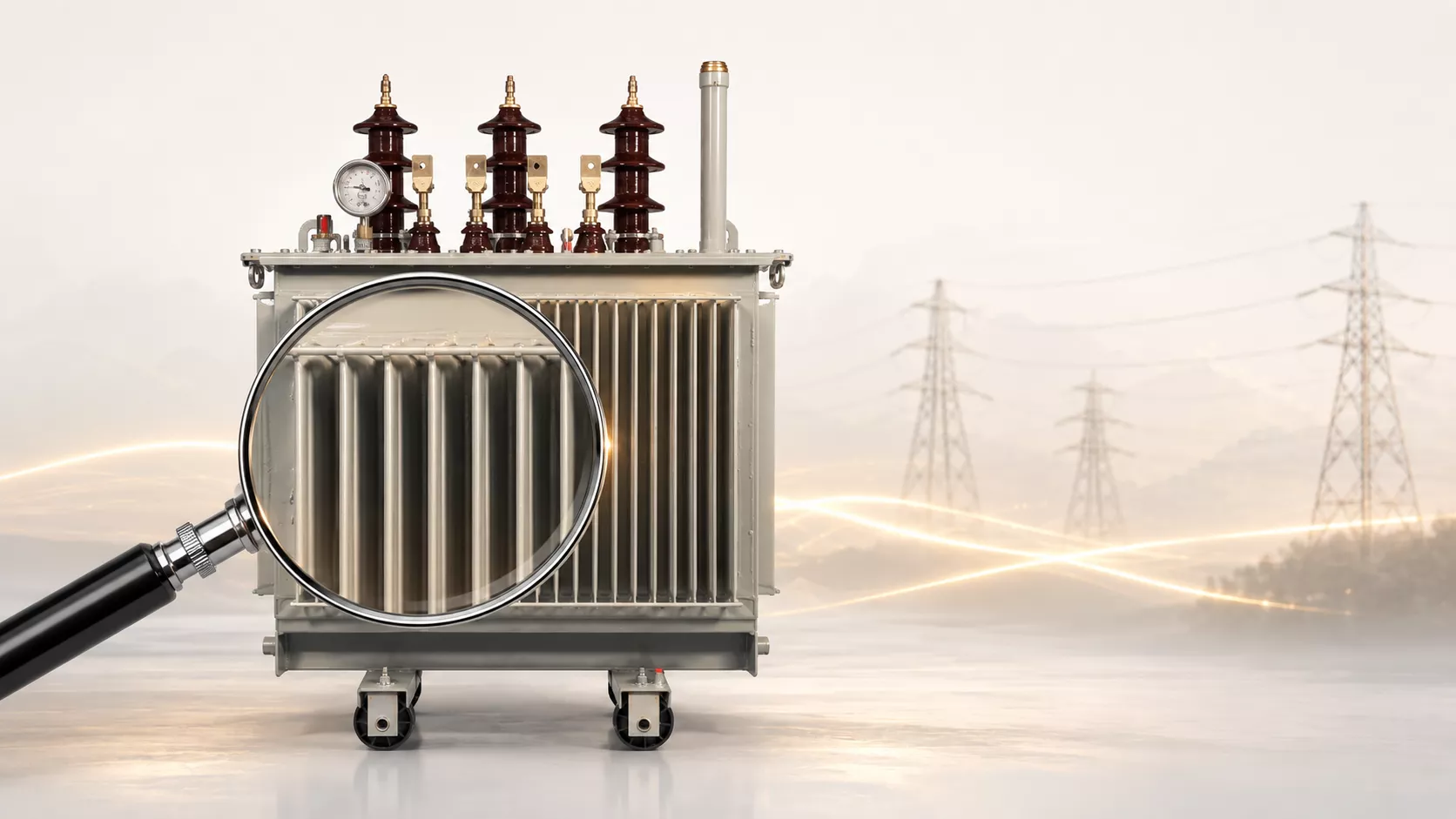
An oil-immersed transformer can stand in one place for decades and transfer energy almost continuously to an industrial plant, a housing estate, a photovoltaic farm, an energy storage system or an electric vehicle charging station.
It has no pistons, shafts or gearboxes that spectacularly rotate during operation.
From the outside, what is most often visible is the steel tank, bushings, radiators, a nameplate and a few control elements.
One might get the impression that not much is happening inside either.
In reality, the transformer is constantly working in a changing magnetic field, carrying large currents and fighting the heat generated in the core and windings.
Every additional ampere, high ambient temperature, and every hour of operation under high load increase the amount of thermal energy that must be effectively removed.
This is precisely why an oil-immersed transformer needs oil.
It is not used to lubricate moving parts, because there are practically none.
Transformer oil performs much more important tasks. It insulates parts under high voltage, absorbs heat from the windings and core, and then transports it to the tank and radiators.
⚡ A transformer does not age solely because the years pass. Its actual durability depends to a very large extent on the temperature at which those years were worked.
This article has been prepared for designers, contractors, investors and those responsible for selecting a transformer for an industrial plant, a renewable energy installation, an energy storage system, a commercial building or critical infrastructure.
We will explain how a transformer transfers energy, where losses come from, how oil can simultaneously cool and insulate, and what distinguishes ONAN and ONAF cooling systems.
We will also show why overloading a transformer by 20% can generate significantly more than 20% additional heat.
Estimated reading time: 9 minutes.
Energy cannot be created from nothing or destroyed irreversibly.
It can, however, be transformed, transmitted, stored and dissipated in various forms.
A power plant therefore does not "produce" energy in the literal sense of the word.
It converts the chemical energy of fuel, solar radiation, wind, water or nuclear reactions into electrical energy.
A transformer performs the next stage of this energy relay.
It does not create new kilowatt-hours, but transfers energy from one circuit to another and changes its parameters so that it can be safely transmitted, distributed and used.
The basic task of a transformer is to change the voltage value of alternating current.
In a typical distribution network, it can step down the medium voltage, for example 15 kV or 20 kV, to the level of 400 V used by machines, building installations, switchgear and other low-voltage consumers.
In other applications, the transformer works in the opposite direction and steps up the voltage. This happens, among other things, in power plants, photovoltaic and wind farms, where the electricity must be transferred to the grid at a level that allows it to be efficiently transported over long distances.
A transformer can be compared to a gearbox in a car. The gearbox does not increase the engine's power, but changes the relationship between rotational speed and torque. A transformer similarly changes the proportions of voltage and current, matching the energy to the conditions prevailing in a given part of the installation.
When the voltage is stepped down, a higher current can flow on the secondary side. When the voltage is stepped up, the current decreases accordingly. In an ideal transformer, the input and output power would be the same. However, a real device always causes some losses, because part of the transmitted energy is dissipated as heat.
A loss of one percent may sound harmless, but for a transformer transmitting 1 MW of power, it corresponds to about 10 kW of heat. That is as if several electric heaters were working inside the steel tank around the clock.
The heat must be removed from the windings and core, and then transferred to the surroundings. Without effective cooling, the temperature of the hottest elements of the transformer would rise quickly, accelerating insulation ageing and shortening the expected service life of the device.
Inside a classic transformer there are the primary winding, the secondary winding and a common magnetic core. The primary winding is connected to the power source, while the secondary winding transfers energy to the rest of the installation.
Both windings are close to each other but are not directly electrically connected. Energy does not flow between them through an ordinary conductor.
Its carrier is the changing magnetic field.
When alternating voltage is applied to the primary winding, current begins to flow through it. A changing magnetic field is created around the winding, which is concentrated and guided by the core. This field also covers the secondary winding and induces a voltage in it.
This phenomenon is called electromagnetic induction.
The most important word here is "changing". A constant magnetic field would not allow continuous induction of voltage in the second winding. That is why a classic transformer works with alternating current.
In the European power grid, the frequency is 50 Hz. The magnetic field in the core therefore constantly changes its value and direction. The core is remagnetised dozens of times every second.
The value of the voltage on the secondary side depends primarily on the turns ratio of the two windings. If the medium-voltage winding has more turns than the low-voltage winding, the transformer steps down the voltage.
For example, changing the voltage from 15,000 V to 400 V corresponds to a voltage ratio of approximately 37.5 to 1. This does not mean, however, that the entire transformer design can be reduced to simple division. The designer must also consider voltage drops, short-circuit voltage, tap regulation, current density, magnetic flux, operating temperature and insulation requirements.
At first glance, a solid steel block might seem a simpler and more durable solution. In a transformer, however, it would cause very large losses.
The changing magnetic field induces currents not only in the secondary winding. Currents can also appear inside the core material. They are called eddy currents.
They can be imagined as small electrical vortices circulating in the steel. They do no useful work. Instead, they heat the core and increase energy consumption.
To limit this phenomenon, the transformer core is made of thin, mutually insulated electrical steel laminations. Each layer interrupts the path along which large eddy currents could circulate. As a result, the amount of heat generated is significantly reduced.
This is not, however, the only source of core losses. The magnetic material must be constantly remagnetised. Its structure does not react to the change of field completely without resistance. This phenomenon is called magnetic hysteresis.
For this reason, a transformer draws a certain amount of energy even when no significant consumer is connected on the secondary side.
The losses occurring in a transformer can be divided into two main groups:
no-load losses and load losses.
No-load losses occur when the transformer is energised.
It does not matter much whether the production plant is running at full capacity or whether all machines have been switched off. As long as the primary winding is energised, the core is remagnetised and losses occur in it.
This can be compared to a car left with the engine running. The vehicle is stationary, but it still consumes fuel.
In the case of a transformer, this means that energy is drawn around the clock, also at night, on weekends and during production stoppages. Therefore, no-load losses are particularly important in facilities where the transformer operates at low load for most of the time.
Even a few hundred watts drawn continuously throughout the year translates into thousands of kilowatt-hours of energy. For larger units, these values can be even higher.
Load losses, on the other hand, occur primarily in the windings and increase with the current flowing through them.
They result from the resistance of the conductor, regardless of whether the winding is made of copper or aluminium.
In the industry, they are often referred to as copper losses, even when the winding is aluminium. The name refers to the type of phenomenon, not always to the actual conductor material.
Load losses increase approximately in proportion to the square of the current. This is one of the most important relationships to understand when selecting and operating a transformer.
If the current increases by 20%, the losses do not increase by 20%. The value 1.2 must be squared, which gives 1.44. This means about 44% more current-dependent losses.
With a current increase of 30%, the result is already 1.69, i.e., about 69% more losses.
In practice, this means that a seemingly small overload can cause a much faster rise in winding temperature. Therefore, a transformer should not be selected "on the edge", considering only the sum of the rated powers of the loads.
The load profile, duration of peaks, ambient temperature, cooling method and the possibility of future system expansion should also be checked.
You might also be interested in this topic:
Transformer oil performs two tasks that at first glance seem completely different.
It must be a good electrical insulator and at the same time effectively transport heat.
In a transformer, there are high voltages and relatively small distances between elements at different potentials. Air also has insulating properties, but oil allows high electrical strength to be achieved in a compact construction.
The liquid fills the spaces between the windings, core, bushings, solid insulation and structural components. It limits the risk of electrical flashover and partial discharges.
At the same time, the oil reaches very close to the surface of the windings – exactly where a significant part of the heat is generated during loading.
It can be described as the transformer's circulatory system.
It absorbs heat from the interior, transports it towards the tank and radiators, releases it to the surroundings, and then returns to the windings for another portion of thermal energy.
Without this circulation, the local temperature of the windings would rise, and the paper insulation and other insulating materials would age much faster.
Properly prepared transformer oil has very good dielectric properties. The problem begins when water, contaminants, solid particles or ageing products appear in it.
Moisture can lower the oil's breakdown voltage and accelerate the degradation of cellulose insulation. High temperature additionally accelerates undesirable chemical reactions.
Inside the transformer, the oil works together with the solid insulation, most often made of paper and pressboard. Cellulosic materials can absorb water. Under the influence of temperature changes, moisture migrates between the paper and the oil.
Therefore, an oil sample is more than just a fragment of liquid taken from the tank. It can be a source of information about the condition of the entire insulation system.
During diagnostics, among other things, the water content, breakdown voltage, acidity, dielectric dissipation factor and gases dissolved in the oil are examined. In some cases, furan compounds are also analysed, which can provide information about the degree of ageing of the cellulose insulation.
Particularly useful is the analysis of dissolved gases, abbreviated as DGA. During local overheating, partial discharges or arcing, characteristic gases can form.
A single result rarely gives a complete answer. What tells the most is the observation of changes over time. If the concentration of certain gases is systematically increasing, it may indicate a developing fault, even if the transformer is apparently still operating correctly.
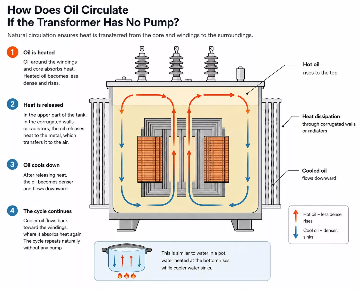
In many distribution transformers, the oil circulation is completely natural.
The oil near the windings and core absorbs heat. As its temperature rises, the density of the liquid decreases slightly. The warmer oil therefore begins to rise upwards.
Its place is taken by cooler and denser oil.
In this way, natural circulation is created. The phenomenon is similar to the movement of water heated in a pot. The water at the bottom heats up, rises, and the cooler part of the liquid sinks.
In a transformer, the flow is directed by appropriately placed oil ducts. The heated oil reaches the upper part of the tank, the corrugated walls or the radiators. There it gives off heat to the metal, which transfers it to the surrounding air.
After cooling, the oil sinks and flows again towards the windings.
The whole process can take place without pumps, provided that the transformer construction, cooling surface and ambient conditions ensure adequate heat exchange performance.
The infographic explains the natural circulation of oil in an oil-immersed transformer without the use of a pump. It shows how heated oil rises around the windings and core, releases heat through the radiators, cools down and sinks, creating a continuous cooling cycle. CC:ENERGEKS 2026
Radiators increase the surface area through which heat can pass from the oil to the air. The larger the heat exchange surface, the more effectively the transformer can cool itself.
Even the best-designed radiator will not work properly, however, if it is deprived of free air flow.
This is one of the problems that appear after the transformer has already been installed.
The device may be positioned too close to a wall. The station room may have too small ventilation openings. Air flow may be restricted by cable routes, additional switchgear or materials stored near the transformer.
In such a situation, the transformer starts to cool itself with air that it has previously heated.
This can be compared to a computer with its ventilation holes taped shut. All the cooling components are still in place, but the hot air cannot be effectively removed.
The temperature inside the station gradually rises, and the difference between the oil temperature and the ambient temperature ceases to be sufficient to dissipate the required amount of heat.
ONAN is one of the most common cooling systems for oil-immersed transformers. The abbreviation comes from the English term Oil Natural Air Natural.
The first word indicates that the insulating and cooling medium is oil. The term "Natural" means that the oil moves inside the transformer due to the natural density difference, without pumps.
The second "Natural" refers to the air flow around the tank and radiators. The air also moves naturally, without fans.
Such a system is simple, quiet and reliable. The absence of fans means fewer elements requiring power, control and maintenance. There are also no motors, bearings or ventilation system protections that could fail.
The limitation is cooling performance. The transformer can only release as much heat as the naturally flowing air can absorb.
Therefore, the same transformer will operate differently in an open space and differently in a tight station with limited ventilation. The ambient temperature also matters. On a hot day, the heat dissipation capability is lower than in winter.
ONAF stands for Oil Natural Air Forced.
The oil inside the transformer still circulates naturally. What changes is the way air flows through the radiators. It is forced by fans.
The fans increase the amount of air flowing over the cooling surfaces, allowing the transformer to release heat to the surroundings more quickly.
They do not, however, change the transformer's ratio, do not increase the winding cross-section and do not create additional electrical energy. They only allow more heat to be removed, which is generated at higher load.
For this reason, some transformers have two power ratings given. The lower one refers to operation in the ONAN system, and the higher one to operation after the fans are switched on in the ONAF system.
This can be compared to a computer processor. An additional fan does not change the number of cores and does not rebuild the electronics. It does, however, allow high performance to be maintained for longer without exceeding the permissible temperature.
The ONAF system requires auxiliary power, temperature sensors, control automation and regular fan checks. If a transformer constantly uses the power available only with forced cooling switched on, a fan failure can quickly become a problem for the entire installation.
You might also appreciate one of the best articles on our blog:
Oil temperature is an important parameter, but it does not always show the full picture.
The highest temperature can occur locally inside the winding. This place is called the hot spot.
It is the hot-spot temperature that is crucial for insulation durability. The oil in the upper part of the tank may still have an acceptable temperature, while in one fragment of the winding the insulation is already significantly hotter.
The temperature distribution is influenced by the winding construction, the arrangement of oil ducts, the load, ambient temperature, the presence of harmonics and the condition of the cooling system.
Two transformers can have a similar oil temperature but a different hottest spot temperature. Therefore, a professional load assessment should not be limited to reading one indicator.
Short-term overload does not necessarily mean immediate failure.
A transformer has a large thermal inertia. The core, windings, tank and oil do not heat up in an instant. If the device was previously operating at a low load, it may have some thermal reserve.
This does not mean, however, that every transformer can be safely overloaded by any value.
The ambient temperature, the initial temperature of the oil and windings, the duration of the overload, the previous operating profile, the device construction, the cooling method and the insulation condition all matter.
A transformer that has operated at 30% load for several hours will behave differently. A unit loaded at 95% all day, enclosed in a hot station during a summer afternoon, will behave differently.
During overload, the losses in the windings rise quickly. First, local fragments of the conductor and insulation heat up. Later, the temperature of the oil, tank and other elements rises.
The most insidious consequence is not always an immediate trip. The transformer may still work, but the elevated temperature accelerates the ageing of the cellulose insulation.
This can be compared to regularly driving a car at very high revs.
The engine does not have to break down on the same day, but its components wear out faster.
In modern installations, rated power does not tell the whole story.
Energy storage systems, photovoltaic farms, inverters, UPS systems, data centres, variable speed drives and electric vehicle charging stations can generate current harmonics.
Harmonics increase additional losses in the windings and metal structural components. They can also cause greater heating of neutral conductors and change the actual temperature distribution in the transformer.
Therefore, the statement "the loads draw 900 kW, so a 1000 kVA transformer will suffice" may be too much of a simplification.
The power factor, load character, harmonic level, simultaneity, load peaks and the planned development of the installation must be checked.
A transformer selected solely on the basis of power may formally meet the requirements and yet operate under unfavourable thermal conditions.
An oil-immersed and a dry-type transformer perform the same basic function.
They use electromagnetic induction to change the voltage value.
They differ primarily in the way the insulation and cooling are implemented.
In an oil-immersed transformer, the core and windings are in an insulating liquid.
The oil increases the electrical strength of the system and dissipates heat directly from the interior of the device.
In a dry-type transformer, the windings are protected by a solid material, often resin, and cooling is mainly by air.
Oil-immersed transformers are often chosen for outdoor operation, at higher powers, and where high efficiency and effective heat dissipation are important.
For their power, they can also have a relatively compact construction.
Dry-type transformers are readily used in buildings, public facilities, shopping centres, hospitals and industrial plants, especially where limiting the amount of insulating liquid is important.
It cannot be said, however, that one technology is always safe and the other always problematic.
An oil-immersed transformer requires proper oil retention, fire protection, an appropriate installation location and fluid condition monitoring.
A dry-type transformer needs effective ventilation, protection against dust and moisture, and suitable thermal conditions.
The choice should result from an analysis of the entire installation, not from a single parameter or a sales slogan.
More on this age-old dilemma can be found in our article:
Let us imagine a plant where the transformer was correctly selected in terms of power. After a few years, production is expanded, but the load still does not exceed the device's rated value.
New cable routes, additional switchgear and structural elements appear in the station room, however. Part of the ventilation openings are restricted, and materials begin to be stored near the radiators.
In winter, the system operates without major problems. In summer, however, the temperature in the station begins to rise.
The transformer is formally not overloaded. Nevertheless, it has an increasing problem with heat dissipation, because the temperature of the cooling air is higher and the flow around the radiators has been restricted.
In such a case, the problem may not be the device's power being too low. The source of the trouble may be the station ventilation.
Replacing the transformer with a larger model without improving the air flow does not solve the cause. The larger device will also have to release heat somewhere.
Therefore, before making a decision, it is worth analysing the actual load profile, the temperature inside the station, the condition of the radiators, the operation of the fans, the freedom of air flow and the presence of harmonics.
Rated power is one of the most important parameters of a transformer, but it cannot be the only selection criterion.
You need to know how long the device will operate close to maximum load, whether short-term peaks occur, what the ambient temperature is, and whether the transformer will be placed inside a building, in a containerised station or outdoors.
It is also important whether the installation includes inverters, chargers, UPS systems and other non-linear loads. The planned expansion, ventilation conditions, permissible noise level and the cost of energy lost over many years of operation should be taken into account.
A transformer may have sufficient power, but at the same time the wrong connection group, short-circuit voltage, loss level, dimensions, terminal arrangement or equipment.
That is why correct transformer selection begins with understanding the installation, not with picking one value from a catalogue.
An oil-immersed transformer can supply factories, housing estates, photovoltaic farms and energy storage systems almost continuously for decades. Although it remains motionless from the outside, inside it the magnetic field, windings and oil – which simultaneously insulates and dissipates heat – are constantly at work.
The best transformer operation is not spectacular.
Conscious transformer selection begins not with browsing a catalogue, but with understanding how the device will operate in a specific installation.
If you have reached this point, you already know that behind the seemingly simple power value also lie losses, temperature, cooling method, installation conditions and the actual load profile.
It is this approach that allows you to avoid random decisions and select a transformer that will operate stably not only on the day of commissioning but also after years of operation.
If you are preparing a new investment, modernising a transformer station or want to verify a previously selected solution, we invite you to contact our team. We will help translate the project's technical requirements into specific device parameters and select a solution appropriate for the operating conditions.
See our full range of oil-immersed and dry-type transformers.
Also check the transformers currently available off-the-shelf – without waiting for the standard production lead time.
And if you are interested in practical materials on transformers, power engineering and installation design, also follow us on LinkedIn. We regularly publish technical knowledge, application examples and tips useful when preparing investments.
Guide for transformer maintenance – 2025 Edition
Shipped from our warehouse in Poland within 2–3 working days, 5-year warranty. Full range 25–2500 kVA in the shop (prices in PLN).
No reviews!